--- 25 ---
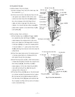
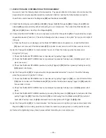
10-4. Disassembly and Reassembly of the Driving Section (See Fig. 20.)
[Tools required]
Hex. bar wrenches (4 mm and 5 mm)
Roll pin pullers (3 mm (.118") dia. and
4 mm (.157") dia.)
Flat-blade head screwdriver with small tip
(a) Disassembly
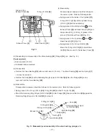
Continuously turn the Adjuster
[38]
in the
direction in which the nail is raised when
adjusting the driving depth (refer to
ADJUSTING THE NAILING DEPTH on
page 21 in the Instruction Manual) so that
Pushing Lever (A)
[40]
can be removed.
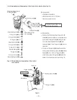
Remove the Hex. Socket Hd. Bolt (W/
Flange) M5 x 20
[78]
with the hex. bar
wrench (4 mm) and remove the two Hex.
Socket Hd. Bolts M6 x 30
[32]
with the
hex. bar wrench (5 mm). Now, the Blade
Guide
[37]
, Guide Plates (A)
[33]
and (B)
[31]
, Pushing Lever (B)
[36]
, etc. can be
removed.
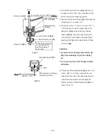
Remove the two Ratchet Springs
[39]
from the Adjuster
[38]
with the small flat-
blade screwdriver being very careful not to
lose them. Now, the Adjuster
[38]
can be
removed from Pushing Lever (B)
[36]
.
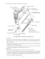
Nylon Nut M5
[44]
Sleeve
[45]
Body Ass’y
[30]
Blade Guide
[37]
Guide Plate
(B)
[31]
Hex. Socket Hd.
Bolt M6 x 30
[32]
Guide Plate
(A)
[33]
Lock Lever
[34]
Roll Pin D3 x 20
[43]
Hex. Socket Hd. Bolt
(W/Flange) M5 x 20
[78]
Roll Pin D3 x 28
[54]
Pushing Lever
Guide
[58]
Roll Pin D4 x 14
[42]
Holder Spring
[35]
Pushing Lever (B)
[36]
Adjuster
[38]
Ratchet Spring
[39]
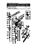
Fig. 20 Disassembly and reassembly of
the driving section
Pushing Lever (A)
[40]
Содержание NT 65MA3
Страница 37: ......

