


--- 21 ---
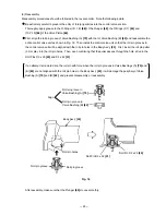
Fig. 12
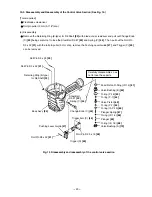
(a) Reassembly
Disassembly procedures should be followed in the reverse order. Note the following points.
Charge the sliding portion of the Head Valve
[9]
of the Exhaust Cover
[5]
with about 3 grams of grease and
apply grease to each surface of the O-rings.
As shown in Fig. 12, firmly push the Exhaust Valve Rubber
[11]
until it is fully seated over the projection of the
Exhaust Cover
[5]
.
Exhaust Cover
[5]
Apply grease of 3 grams
to the sliding portion.
Head Valve
[9]
Exhaust Valve Rubber
[11]
Push until the rubber is fully
seated over the projection.
Mount the Sheet
[3]
in the direction as shown in Fig. 13 aligning the center of the hole of the Sheet
[3]
with the
center of the bolt hole of the Exhaust Cover
[5]
. If not aligned, abnormal exhaust noise may be heard.
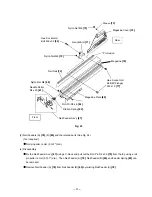
Fig. 13
Sheet
[3]
Exhaust Cover
[5]
Align the center of the hole of
the Sheet
[3]
with the center
of the bolt hole of the Exhaust
Cover
[5]
.
Содержание NR 90AE (S)
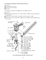
Страница 33: ... 30 Fig 23 Magazine section Nail Feeder Ass y 87 Nose 28 Magazine 76 0 05 max 1 3 mm max ...
Страница 42: ......