


--- 20 ---
Hex. Socket Hd. Bolt
(W/Flange) M6 x 30
[4]
Sheet
[3]
Hex. Socket Hd. Bolt
M5 x 14
[1]
Exhaust Cover
[5]
O-ring (I.D. 49.4)
[8]
Exhaust Valve Rubber
[11]
Head Guard
[2]
Head Valve Spring
[7]
O-ring (I.D. 59.4)
[10]
Head Valve
[9]
Gasket (A)
[6]
Body Ass'y
[24]
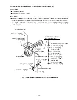
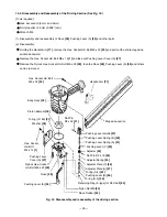
10-2. Disassembly and Reassembly of the Output Section
(1) Disassembly and reassembly of the Exhaust Cover
[5]
, Head Valve
[9]
, Exhaust Valve Rubber
[11]
, etc.
(See Fig. 11A and Fig. 11B.)
Fig. 11B
Fig. 11A Disassembly and reassembly of the
exhaust cover, head valve, exhaust
valve rubber, etc.
Exhaust Cover
[5]
Exhaust Valve
Rubber
[11]
Bar of 4 to 5 mm dia.
Hammer
[Tools required]
Hex. bar wrench (4 mm, 5 mm)
Hammer
(a) Disassembly
Remove the four Hex. Socket Hd. Bolts M5 x 14
[1]
with a
hex. bar wrench. The Head Guard
[2]
and the Sheet
[3]
can now be removed.
Remove the four Hex. Socket Hd. Bolts (W/Flange)
M6 x 30
[4]
with a hex. bar wrench. The entire Exhaust
Cover
[5]
can now be removed from the Body Ass'y
[24]
.
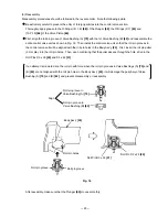
As shown in Fig. 11B, insert a 4 to 5 mm dia. bar into the
central hole in the Exhaust Cover
[5]
and force out the
Exhaust Valve Rubber
[11]
with a hammer. Now, the
parts forming the Exhaust Valve Rubber
[11]
can be
taken out.
[CAUTION]
To prevent damage to the Exhaust Valve Rubber [11], do
not use a pointed bar or a bar with a diameter of less
than 4 mm.
Содержание NR 90AE (S)
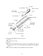
Страница 33: ... 30 Fig 23 Magazine section Nail Feeder Ass y 87 Nose 28 Magazine 76 0 05 max 1 3 mm max ...
Страница 42: ......