--- 22 ---
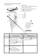
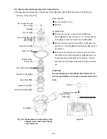
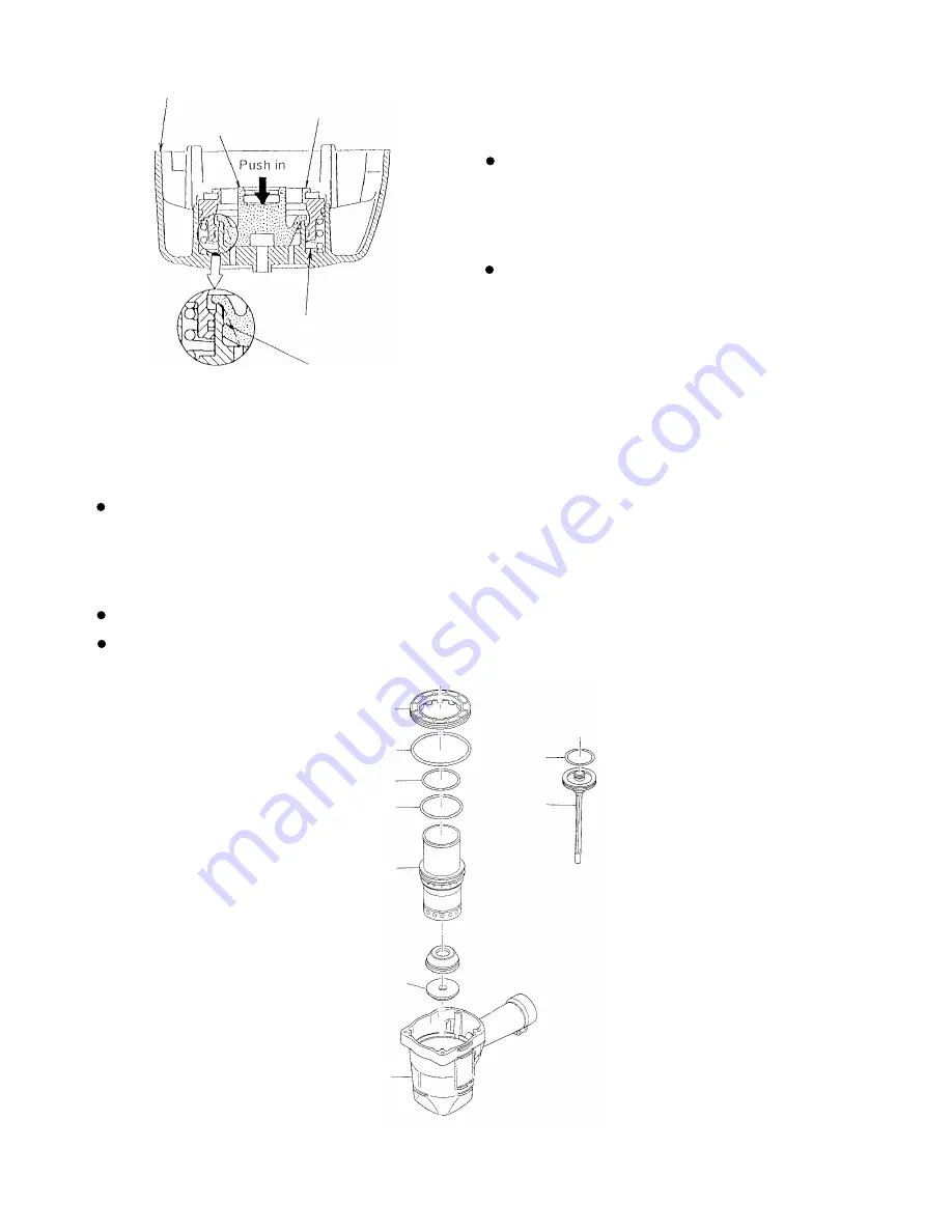
Fig. 12
Cylinder [17]
Body [22]
Cylinder Plate [13]
(b) Reassembly
Disassembly procedures should be followed in the
reverse order. Note the following points.
Charge the sliding portion of the Head Valve [10]
of the Exhaust Cover [5] with about 3 grams of
grease and apply grease to each surface of the
O-rings.
As shown in Fig. 12, firmly push the Exhaust Valve
Rubber [7] until it is fully seated over the
projection of the Exhaust Cover [5].
Exhaust Cover [5]
Charge with grease of 3 grams.
Head Valve [10]
Exhaust Valve
Rubber [7]
Push until the rubber is fully
seated over the projection.
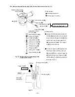
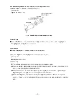
(2) Disassembly and reassembly of the Cylinder [17], Piston [19], Piston Bumpers (A), (B) [24], [25], etc.
(See Fig. 13.)
(a) Disassembly
Remove the Exhaust Cover [5] as described in item (1). Now, the Cylinder [17], Cylinder Plate [13], Piston
[19], Piston Bumpers (A), (B) [24], [25], etc. can be taken out.
(b) Reassembly
Disassembly procedures should be followed in the reverse order. Note the following points.
Apply designated grease to the O-ring (1AP-48) [18] and the internal side of the Cylinder [17].
Apply designated grease to the O-ring (S-95) [14], O-ring (I.D 59.6/W2.4) [15] and the O-ring [16], and then
install them.
Fig. 13 Disassembly and reassembly of the cylinder, piston, piston bumper, etc.
Piston Bumper (A) [24]
O-ring (S-95) [14]
O-ring (I.D. 59.6/W2.4) [15]
O-ring [16]
Piston Bumper (B) [25]
O-ring
(1AP-48)
[18]
Piston
[19]
Содержание NR 90AC3
Страница 39: ......


