5
11
x 4
x 2
12
x 1
Bottom Chassis
Bass/Treble Knob
Master Vol.
Front Panel
13
13
x 1
16
x 2
x 1
14
x 11
15
x 2
Nut x 2
Nut x 1
Inner Panel
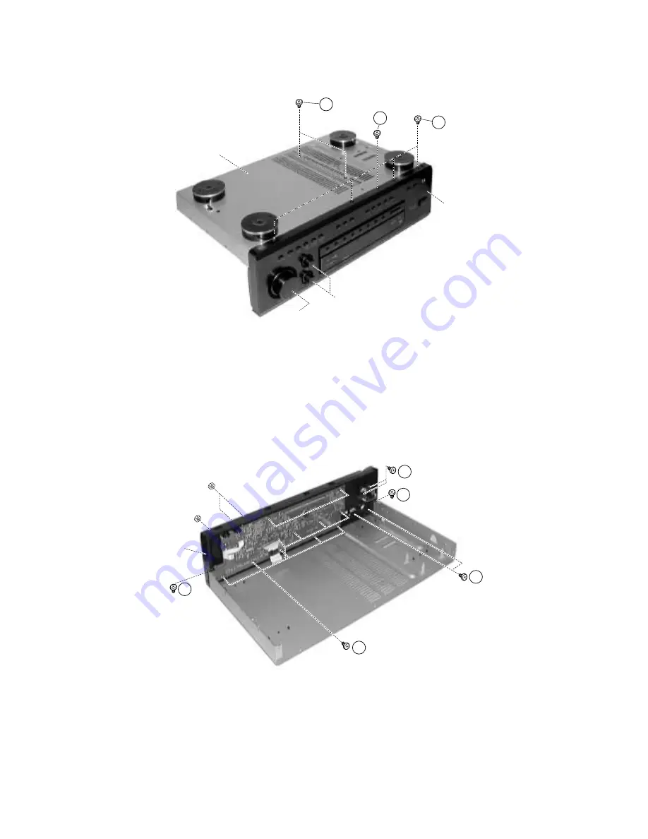
8. Removal of Front Panel
(a)Invert the Bottom Chassis and remove 4 screws ".
(b)Remove the Master Vol. & Bass/Treble Knob before remove the Front panel.
9. Removal of Inner Panel, Power Switch, Phone
Jack and FL PWB
(a)Release the inner panel from the Bottom Chassis by remove 1 screw # (Fig. 5) and 2 screws $.
(b)Remove 11 screws % and 3 nuts to release the FL board.
(c)Remove 2 screws & to release the Power Switch.
(d)Remove 2 screws ( to release the Phone Jack.
Fig. 5
Fig. 6
Содержание HTA-DD1E
Страница 8: ...17 x 4 10 Removal of Foot a Remove 4 screws to remove foot Fig 7 ...
Страница 11: ...SM0102 WIRING DIAGRAM ...
Страница 12: ......
Страница 13: ...SM0102 TUNER PCB ...
Страница 14: ...SM0102 SURR PCB ...
Страница 15: ...SM0102 DSP PCB ...
Страница 16: ...SM0102 FL PCB ...
Страница 17: ...SM0102 POWER PCB ...
Страница 18: ...SM0102 VIDEO PCB ...
Страница 19: ...SM0102 SPJK PCB ...
Страница 20: ...SM0102 SW H P PCB ...
Страница 21: ...SM0102 DIGITAL IN PCB ...
Страница 22: ...SM0102 MAIN CIRCUIT ...
Страница 23: ...SM0102 DISP TONE CIRCUIT ...
Страница 24: ...SM0102 SURROUND MAIN AMP CIRCUIT ...
Страница 25: ...SM0102 TUNER VOLUME CIRCUIT ...
Страница 26: ...SM0102 DSP CIRCUIT ...
Страница 27: ...SM0102 POWER SUPPLY VIDEO CIRCUIT ...
Страница 28: ......
Страница 45: ...MEMO ...


