background image

ENGLISH

15

HAS-WM05

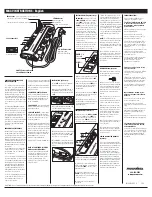
1. Fine adjustment of horizontal 

position

2. Fine adjustment of horizontal 

keystone

3. Fine adjustment of vertical 

keystone

4. Fine adjustment of lateral 

position

5. Fine adjustment of image size

6. Fine adjustment of focus

  For details, see the User’s Manual for the LCD projector.

  #

-2. Make a rough focus adjustment.

  For details, see the User’s Manual for the LCD projector. 

  #

-3. Make fine adjustments. 

  Loosen fastening screws (1) to (4). 

  Follow the steps below to turn the adjusting screws and adjusting knobs to adjust the image. 

(Blue)

(Red)

(Green)

Red

Green

Blue

Use the included hex wrench (O).

3

4

5

1

2

(1)

(2)

(4)

(3)

14

HAS-WM05

#

 Adjust the image.

  #

-1. Adjustment of image size.

1.    Slide the arm forward and backward to adjust image size. 

A

B

Scale

Adjustment screw, center

Adjustment screw (hex-head screw)

Align the center of the adjustment screw (hex-head screw) to the scale to 

adjust for the required screen size.

Содержание HAS-WM05

Страница 1: ...g these documents put them away in a safe place for future reference Disclaimer 1 Table of Contents 1 Safety Symbols 1 Overview 2 Installation Precautions 2 Tools needed for installation 2 To the customer 3 To service personnel 3 Routine Inspections 3 Contents of this package 4 Base bracket attachment diagram 5 Template sheet usage 6 Installation procedure 7 1 Wall mounting of the base assembly 7 ...

Страница 2: ...t the back of the projector to enable air to enter via the air intake 5 Do not install the projector in a location exposed to sudden temperature changes for example near air conditioners or where the temperature rises above 40 C 3 Do not install the projector in a smoke filled or extremely dusty environment as the tar in cigarette smoke will settle on the optics and lower performance 4 Do not inst...

Страница 3: ...d brackets are used in the installation Considerable care is required in planning and performing the installation so that it will support the weight of the LCD projector and wall mount unit Never attempt to modify the wall mount unit We will not guarantee the strength of a unit that has been modified Make sure that all screws are tightened to the proper torque after installation and adjustments Th...

Страница 4: ... block 1 M Strut cover bracket 2 E Bracket 1 N M5 shoulder screw 3 F Front cap 1 O Allen wrench 1 G Cable cover middle 1 P Template sheet 1 H Cable cover left 1 Q User s Manual This book 1 I Cable cover right 1 R M4 x 20mm cover mounting screws 1 Arm bracket IN Arm bracket OUT 34 6 16 10 screen 1 36 c3 a Wall Hole Center a c3 Diagonal size inches 60 70 80 90 100 mm inches 279 3 11 00 317 3 12 49 3...

Страница 5: ... 77 70 170 6 69 242 9 53 1309 51 54 213 3 8 40 338 3 13 32 384 6 15 14 169 5 6 67 80 236 9 29 265 10 43 1484 58 43 236 3 9 30 361 3 14 22 450 6 17 74 192 5 7 58 90 302 11 89 288 11 34 1660 65 35 259 3 10 21 384 3 15 13 516 6 20 34 215 5 8 48 100 368 14 49 310 12 20 1834 72 20 281 3 11 07 406 3 16 00 582 6 22 94 237 5 9 35 1 For a 50 mm thick screen Size of images that can be projected with screen ...

Страница 6: ...0 80 90 100 110 120 130 140 150 160 170 180 190 200 210 220 230 240 250 260 270 280 290 300 310 320 330 340 350 360 370 380 390 400 410 420 430 440 0 10 20 30 40 50 60 70 80 90 100 110 120 130 140 150 160 170 180 190 200 210 220 230 240 250 260 270 280 290 300 310 320 330 340 350 360 370 380 390 400 410 420 430 440 0 Template sheet usage Determining location of wall holes Place the template sheet ...

Страница 7: ...bolts Base bracket center B at least 4 places Base brackets side C at least 2 places on each WARNING When attaching the wall mount unit to a wall covered with a layer of plaster or other weak finishing material make sure the anchor bolts reach into the underlying concrete As shown in the figure at least eight anchor bolts two in each corner are required Concrete Concrete Weak material Weak materia...

Страница 8: ...n as indicated in the diagram Tightening torque 0 98 N m 10 kgf cm CAUTION Assemble the adjusting block D according to projection screen size Projection screens smaller than 70 inches Projection screens 70 inches or larger Note Face the knobs of the adjustment block D in the directions shown in this diagram Arm bracket IN Adjusting block D Fastening screw Arm bracket IN Arm bracket IN Adjusting bl...

Страница 9: ... 5 Mount the arm assembly A on the base bracket assembly Red mark Red mark M10 x 152mm Arm vertical adjustment screw L Arm assembly A Base bracket assembly Arm assembly A Temporarily suspend the arm assembly A from the screws Screw Hook the groove of the screw on the U shape of the base bracket assembly 1 2 n the block o the r ...

Страница 10: ...en them with a hex wrench O and fasten the arm assembly A Two places 7 Fasten the strut cover bracket M with the M4 x 8mm hex head screws J Two places M10 x 194mm Arm fixing strut screw K Two places M10 x 194mm Arm fixing strut screw K M10 x 194mm Arm fixing strut screw K Strut cover bracket M Two places M4 8 hexagon head screws J Two places ...

Страница 11: ...lace cushioning material on a workbench Turn over the projector and place it upside down on the cushioning material on the workbench Note Make sure that the bracket E is correctly oriented Face the cut out part toward the cable connection side WARNING Never use screws other than those designated Failure to heed this warning may cause the projector to fall or other hazard resulting in damage or inj...

Страница 12: ...M4 x 8mm hex head screw J Tightening torque 0 98 N m 10 kgf cm Connect the cables to the projector WARNING Never use screws other than those designated Failure to heed this warning may cause the projector to fall or other hazard resulting in damage or injury projector rear panel Adjusting block D M4 8 hexagon head screw J One place Bracket E Projector N J M5 shoulder screws N Three places If passe...

Страница 13: ...uttons to select the ADVANCED MENU 4Use the cursor buttons to select SCREEN 5Use the cursor buttons to select HAS WM05 in the illustrated template Press the ENTER button to display the selected HAS WM05 TEMPLATE ENTER button Cursor button Menu button EASY MENU ADVANCED MENU VIDEO DOC CAMERA KEYSTONE ASPECT SEARCH BLANK MUTE MY BUTTON POSITION 1 2 ESC ENTER MENU RESET COMPUTER MY SOURCE AUTO MAGNIF...

Страница 14: ...S WM05 Adjust the image 1 Adjustment of image size 1 Slide the arm forward and backward to adjust image size A B Scale Adjustment screw center Adjustment screw hex head screw Align the center of the adjustment screw hex head screw to the scale to adjust for the required screen size ...

Страница 15: ...age size 6 Fine adjustment of focus For details see the User s Manual for the LCD projector 2 Make a rough focus adjustment For details see the User s Manual for the LCD projector 3 Make fine adjustments Loosen fastening screws 1 to 4 Follow the steps below to turn the adjusting screws and adjusting knobs to adjust the image Blue Red Green Red Green Blue Use the included hex wrench O 3 4 5 1 2 1 2...

Страница 16: ...n Repeat steps 1 to 7 to fine adjust the image to the screen See page 20 for details on adjustment range 4 Tighten the five loosened fastening screws 1 to 5 A B Turn the height adjusting screw to adjust the height A B Supplied Allen wrench O Use the included hex wrench O 1 2 4 5 3 ...

Страница 17: ...cket IN Hook the tabs on either side in the holes in the arm bracket IN 2 Attach the cable cover Insert the two tabs 1 and 2 in the cable cover with the two holes 1 and 2 in the LCD projector Secure the cable cover screw 3 to the LCD projector 3 Front cap F Tab Hole 1 2 3 1 2 3 Route the cables through the holes in the top of the cable cover ...

Страница 18: ...first 3 Attach cable cover H and fasten it with the one M4 x 20mm cover mounting screw R Attaching the cable cover Cable cover G M4 8 hexagon head screws J Two places Cable cover I Hook the tab in the hole in the base bracket side Fit the hole onto the screw head Hole Screw head Hook the tab in the hole in the base bracket side Hole Cable cover H Fit the hole onto the screw head Screw head honnyak...

Страница 19: ...nts Make sure that the keystone control is set to 0 no correction before starting adjustments It takes about 30 minutes for lamp performance to stabilize and a change in environment may cause subtle changes in projection location and focus Make proper adjustments to compensate for changes in focus Note Changes in temperature humidity and other ambient environmental factors may result in changes in...

Страница 20: ...thod Fine adjustment of horizontal position 5 page 15 Fine adjustment of horizontal keystone 5 page 15 Fine adjustment of vertical keystone 5 page 15 Fine adjustment of lateral position 50 mm 1 96 inches page 15 Fine adjustment of image size 308 mm 12 1 inches page 15 Fine adjustment of vertical position 35 mm 1 37 inches page 16 Adjustment specifications ...

Страница 21: ...orted Hitachi LCD projector models Model Screen size Weight LCD projector model A CP AX2503 CP AX3003 CP AX3503 4 3 Approx 4 2kg CP AW2503 CP AW3003 CP TW2503 CP TW3003 16 10 Wall mount unit HAS WM05 Approx 6 4kg on of method 15 15 15 15 15 16 ...

Отзывы: