background image

9

English

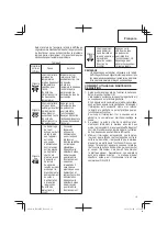
12.  About the protection function


This tool has a built-in protection circuit for preventing 

damage to the unit in the event of an abnormality. 


Depending on the nature of the abnormality, the display 

lamp will 

fl

 ash as shown in Table 2 and the unit will 

cease to operate. In such cases, verify the problem 

indicated by the 

fl

 ashing and take whatever steps are 

necessary to correct the problem.

Table 2

Display 

lamp 

fl

 ashing

Cause

Solution

Flash

The tool has 

shut down 

due to internal 

temperatures 

which exceed the 

unit’s speci

fi

 ed 

temperature.

(Temperature 

increase protection 

function)

Turn o

  the tool and 

allow it to cool down 

for about 15 to 30 

minutes. 

Once the temperature 

is down, the unit will 

recover when the 

impact rate selector 

switch is pressed.

Flash

The tool has 

shut down due 

to an overload 

resulting from 

the application of 

excessive pressure 

to the unit.

(Overload 

protection function)

Press the impact rate 

selector switch to 

recover. Try to avoid 

tasks that will apply 

excess pressure to 

the unit.

Flash

1

  Tool fails to 

startup or has 

shut down due 

to the unit being 

connected to a 

power source 

whose voltage 

is either too high 

or too low.

2

  Tool has shut 

down due to a 

voltage signal 

read error that 

occurred from 

the unit’s power 

cord being 

plugged in and 

out at short 

intervals.

(Circuit protection 

function)

1

  Connect the unit 

to a power supply 

matching the input 

voltage speci

fi

 ed 

on the nameplate. 

Press the impact 

rate selector switch 

to recover.

2

  Allow for an interval 

of 3 seconds 

or more when 

plugging the power 

cord in and out. 

Press the impact 

rate selector switch 

to recover.

Flash

Tool fails to startup 

or has shut down 

due to a sensor 

signal read error.

(Control monitoring 

function)

Press the impact rate 

selector switch to 

recover. Repair may 

be required if this error 

continuously occurs.

NOTE


Repair may be required if the display lamp continues 

to 

fl

 ash after taking all necessary steps to correct the 

problem. If the problem persists, please arrange for 

repairs.

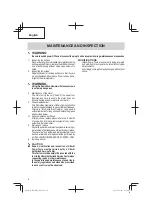
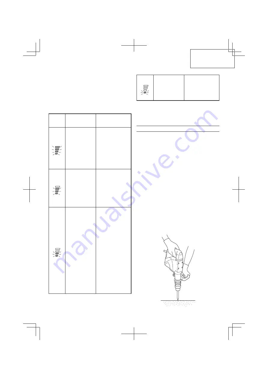
HOW TO USE THE DEMOLITION HAMMER

1.  After placing the tip of the tool on concrete surface, 

switch ON.


The switch can be turned ON if the trigger is pulled and 

OFF when it is released.


If the ON-Lock switch is pressed while the trigger for 

the switch is pulled, even if your 

fi

 nger is released from 

the trigger, the switch remains ON - convenient for 

continuous operation.


To turn the switch OFF, pull the trigger again, and then 

the ON-Lock switch comes o

 .

2.  By utilizing the empty weight of the machine and by 

fi

 rmly holding the hammer by both hands, you can 

e

 ectively control the subsequent recoil motion.


Proceed at a moderate work-rate, the use of too much 

pushing force will impair e

  ciency.

3.  Even when the switch is on, the motor is running and 

the tool head is pressed to the demolition surface, 

the hammer sometimes does not start operating. In 

these instances, turn the switch o

 , press the tool 

head against the demolition surface again, and turn 

the switch on and o

 . This should start the hammer 

operating. Repeat this procedure for several minutes, 

and the hammer will heat, after which it will operate 

when switched to ON-LOCK.

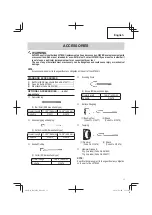
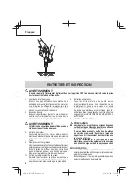
Fig. 10

000Book̲H45MEY̲NA.indb   9

000Book̲H45MEY̲NA.indb   9

2016/06/09   17:38:43

2016/06/09   17:38:43

Содержание H 45MEY

Страница 1: ...es Ce mode d emploi contient d importantes informations à propos de la sécurité de ce produit Prière de lire et de comprendre ce mode d emploi AVANT d utiliser l outil motorisé Garder ce mode d emploi à la disponibilité des autres utilisateurs et propriétaires avant qu ils utilisent l outil motorisé Ce mode d emploi doit être conservé dans un endroit sûr INSTRUCCIONES DE SEGURIDADY MANUAL DE INSTR...

Страница 2: ... POUR UN FONCTIONNEMENT PLUS SUR 15 DESCRIPTION FONCTIONNELLE 16 NOM DES PARTIES 16 SPECIFICATIONS 16 ASSEMBLAGE ET FONCTIONNEMENT 17 APPLICATIONS 17 AVANT L UTILISATION 17 COMMENT UTILISER LE MARTEAU DE DEMOLITION 19 ENTRETIEN ET INSPECTION 20 ACCESOIRES 21 ACCESSOIRES STANDARD 21 ACCESSOIRES SUR OPTION 21 LISTE DES PIECES 32 INFORMACIÓN IMPORTANTE SOBRE SEGURIDAD 22 SIGNIFICADO DE LAS PALABRAS D...

Страница 3: ...ery operated cordless power tool 1 Work area safety a Keep work area clean and well lit Cluttered or dark areas invite accidents b Do not operate power tools in explosive atmospheres such as in the presence of flammable liquids gases or dust Power tools create sparks which may ignite the dust or fumes c Keep children and bystanders away while operating a power tool Distractions can cause you to lo...

Страница 4: ...the power tool or these instructions to operate the power tool Power tools are dangerous in the hands of untrained users e Maintainpowertools Checkformisalignment orbindingofmovingparts breakageofparts and any other condition that may affect the power tool s operation If damaged have the power tool repaired before use Manyaccidentsarecausedbypoorlymaintained power tools f Keep cutting tools sharp a...

Страница 5: ...ly handle power tools Should a power tool be dropped or struck against hard materials inadvertently it may be deformed cracked or damaged 20 Do not wipe plastic parts with solvent Solvents such as gasoline thinner benzine carbon tetrachloride and alcohol may damage and crack plastic parts Do not wipe them with such solvents Wipe plastic parts with a soft cloth lightly dampened with soapy water and...

Страница 6: ...lunlessyouhavefirstreadandunderstoodallsafeyinstructions contained in this manual Some illustrations in this Instruction Manual may show details or attachments that differ from those on your own power tool NAME OF PARTS Nameplate Side handle Front cap Grip B Grip Tail cover Housing ON Lock switch Trigger switch Motor internal Handle Bull Point SDS max shank Power lamp Display lamp Impact rate selec...

Страница 7: ...ely accepts the plug the receptacle must be repaired Contact a licensed electrician to make appropriate repairs If such a fautly receptacle is used it may cause overheating resulting in a serious hazard 5 Confirming condition of the environment Confirm that the work site is placed under appropriate conditions conforming to prescribed precautions 6 How to install tool CAUTION For tools such as a bu...

Страница 8: ... 7 3 Turn the grip in the direction of Ⓑ and fix the handle Ⓐ Fig 4 Fig 6 Fig 5 Fig 7 Grip Ⓑ 10 Power lamp The power lamp lights up when the power cord is plugged into an electrical outlet Fig 8 Fig 8 Power lamp 11 Regulating the number of hammering Fig 9 This Demolition Hammer is equipped with a built in electronic control circuit that can adjust and regulate the number of times of hammering This...

Страница 9: ...ds or more when plugging the power cord in and out Press the impact rate selector switch to recover Flash Tool fails to startup or has shut down due to a sensor signal read error Control monitoring function Press the impact rate selector switch to recover Repair may be required if this error continuously occurs NOTE Repair may be required if the display lamp continues to flash after taking all nec...

Страница 10: ...litionHammerisoffullair tightconstruction toprotectagainstdustandtopreventlubricantleakage Therefore this Demolition Hammer can be used withoutlubricationforlongperiods Replacethegrease as described below Grease Replacement Period After purchase replace grease after every 6 months of usage Ask for grease replacement at the nearest authorized Service Center 5 Service and repairs Allqualitypowertool...

Страница 11: ...7 2 Shank Code No 313479 Tamping 1 Rammer Code No 313478 2 Shank Code No 313479 Hammer Grease A 30 g in a tube Code No 981840 70 g in a tube Code No 308471 NOTE Specificationsaresubjecttochangewithoutanyobligation on the part of the HITACHI ACCESSORIES WARNING ALWAYS use Only authorized HITACHI replacement parts and accessories NEVER use replacement parts or accessories which are not intended for ...

Страница 12: ...rcesavertissementsetinstructionspeutengendrerdeschocsélectriques desincendies et ou des blessures graves Conservez tous les avertissements et toutes les instructions pour vous y référer ultérieurement Le terme outil électrique utilisé dans les avertissements se réfère aux outils électriques câblé ou aux outils à piles sans fil 1 Sécurité de l aire de travail a Maintenir l aire de travail propre et...

Страница 13: ...En cas de dispositifs destinés au raccordement d installations d extraction et de recueil de la poussière veiller à ce qu ils soient correctement raccordés et utilisés L utilisation d un dispositif de collecte de la poussière peut réduire les dangers associés à la poussière 4 Utilisation et entretien d un outil électrique a Ne pas forcer sur l outil électrique Utiliser l outil électrique adapté à ...

Страница 14: ...non autorisé 12 Maintenir toutes les vis tous les boulons et les couvercles fermement en place Maintenir toutes les vis tous les boulons et les couverclesfermementmontés Vérifierleursconditions périodiquement 13 Nepasutiliserlesoutilsmotoriséssilerevêtement de plastique ou la poignée est fendu Des fentes dans le revêtement ou la poignée peuvent entraîner une électrocution De tels outils ne doivent...

Страница 15: ...ur C est pourquoi le symbole ou les mots Double insulation double isolation apparaissent sur l outil motorisé ou sur la plaque signalétique Bien que ce système n ait pas de mise à terre extérieure il est quand même nécessaire de suivre les précautions de sécurité électrique données dans ce mode d emploi y compris de ne pas utiliser l outil motorisé dans un environnement humide Pour garder le systè...

Страница 16: ...u des accessoires différents de ceux de l outil motorisé utilisé NOM DES PARTIES Moteur interne Commutateur Marche Verrouillage Poignée Témoin d affichage Témoin d alimentation Capuchon avant Poignée B Poignée Poignée latérale Pointe de broyage Tige SDS max Plaque signalétique Gâchette Carter Couvercle arrière Sélecteur du taux de percussion Fig 1 SPECIFICATIONS Modèle H45MEY Moteur Moteur sans balai...

Страница 17: ...imentation qui doit être utilisée est conforme à la source d alimentation requise spécifiée sur la plaque signalétique du produit 2 Interrupteur d alimentation S assurer que l interrupteur est sur la position OFF arrêt Si la fiche est connectée sur une prise alors que l interrupteur est sur la position ON marche l outil motorisé démarrera immédiatement risquant de causer de sérieuses blessures 3 C...

Страница 18: ...rdon d alimentation est branché dans une prise électrique Fig 8 Fig 8 Témoin d alimentation 11 Réglage de la fréquence de percussion Fig 9 Ce marteau de démolition est équipé d un circuit de commande électronique incorporé capable d ajuster et de réguler la fréquence de percussion Ce marteau de démolition peut être utilisé en ajustant le sélecteur du taux de percussion selon la nature de l opérati...

Страница 19: ...tionnement Clignote L outil ne parvient pas à démarrer ou s est arrêté en raison d une erreur de lecture du signal du capteur Fonction de contrôle Appuyez sur le sélecteur du taux de percussion pour rétablir le fonctionnement Un dépannage peut s avérer nécessaire si l erreur se répète REMARQUE Un dépannage peut s avérer nécessaire si le témoin d affichage continue à clignoter même après avoir pris l...

Страница 20: ...rès technologiques En conséquence il est possible que certaines pièces soient modifiées sans avis préalable 1 Contrôle du foret de perçage Etant donné que l utilisation d une mèche usée entraînera un mauvais fonctionnement du moteur et une diminution de l efficacité remplacez la mèche usée par une neuve ou aiguisez la immédiatement et dès que vous notez une certaine usure 2 Inspection des vis Inspec...

Страница 21: ... de code 313477 2 Queue No de code 313479 Bourrage 1 Bourroir No de code 313478 2 Queue No de code 313479 Graisse A pour marteau 30 g en tube No de code 981840 70 g en tube No de code 308471 REMARQUE Les spécifications sont sujettes à modification sans aucune obligation de la part de HITACHI ACCESSOIRES STANDARD 1 Pointe de broyage Tige SDS max No de code 313471 1 2 Boîter No de code 337594 1 3 Po...

Страница 22: ...odría producirse una descarga eléctrica un incendio y o daños graves Guarde todas las advertencias e instrucciones para futura referencia El término herramienta eléctrica en las advertencias hace referencia a la herramienta eléctrica que funciona con la red de suministro con cable o a la herramienta eléctrica que funciona con pilas sin cable 1 Seguridad en el área de trabajo a Mantenga la zona de ...

Страница 23: ...zan adecuadamente La utilización de un sistema de recogida de polvo puede reducir los riesgos relacionados con el polvo 4 Utilización y mantenimiento de las herramientas eléctricas a No fuerce la herramienta eléctrica Utilice la herramienta eléctrica correcta para su aplicación La herramienta eléctrica correcta trabajará mejor y de forma más segura si se utiliza a la velocidad para la que fue dise...

Страница 24: ...memente fijados en su lugar Mantenga todos los tornillos pernos y cubiertas firmemente montados Compruebe periódicamente su condición 13 No utilice herramientas eléctricas si la carcasa o la empuñadura de plástico está rajada Las rajas en la carcasa o en la empuñadura de plástico pueden conducir a descargas eléctricas Tales herramientas no deberán utilizarse mientras no se hayan reparado 14 Las cu...

Страница 25: ...manejado por el operador Por lo tanto en la herramienta eléctrica o en su placa de características aparecen el símbolo o las palabras Double insulation aislamiento doble Aunque este sistema no posee puesta a tierra externa usted deberá seguir las precauciones sobre seguridad eléctrica ofrecidas en este Manual de instrucciones incluyendo la no utilización de la herramienta eléctrica en ambientes hú...

Страница 26: ...a los de la propia herramienta eléctrica NOMENCLATURA Interruptor disparador Cubierta del extremo Punta Vástago SDS máximo Alojamiento Mango Lateral Placa de características Tapa frontal Empuñadura B Empuñadura Mango Lámpara de la pantalla Lámpara de encendido Motor interno Interruptor de bloqueo de encendido Interruptor selector de velocidad de impacto Fig 1 ESPECIFICACIONES Modelo H45MEY Motor M...

Страница 27: ...rserecalentamiento loquesupondríaunriesgo serio 5 Confirme las condiciones del medio ambiente Condirmequeellugardetrabajoestéenlascondiciones apropiadasdeacuerdoconlasprecaucionesdescritas 6 Montaje de la herramienta PRECAUCIÓN Para herramientas como un cincel utilice únicamente partes genuinas de Hitachi 1 Limpiar y engrasar la espiga con la grasa o aceite de máquina 2 Parafijarlaherramienta espi...

Страница 28: ...tor de velocidad de impactomientraselmotorestárotando Paracambiarla velocidad de impacto apague primero la herramienta Empuñadura B Fig 3 2 Suelte la empuñadura B gire la herramienta y cerciórese de que haya quedado completamente bloqueada 8 Extracción de la herramienta TalcomosemuestraenlaFig 2 tiredelaempuñadura y extraiga la herramienta PRECAUCIÓN Asegúrese de sujetar la empuñadura y la empuñad...

Страница 29: ...ha desconectado a causa de un error de lectura de la señal del voltaje producido por enchufar y desenchufar el cable de alimentación de la unidad en intervalos breves función de protección del circuito 1 Conecte la unidad a una fuente de alimentación que coincida con la tensión entrante especificada en la placa de identificación Presione el interruptor selector de velocidad de impacto para recuper...

Страница 30: ...en ser realizadas por un Centro de Servicio Autorizado de Hitachi Esta lista de repuestos será de utilidad si es presentada junto con la herramienta al Centro de Servicio Autorizado de Hitachi para solicitar la reparaciónocualquierotrotipodemantenimiento En el manejo y el mantenimiento de las herramientas eléctricas se deberán observar las normas y reglamentos vigentes en cada país MODIFICACIONES ...

Страница 31: ...13477 2 Barrena Núm de código 313479 Apisonamiento 1 Pisón Núm de código 313478 2 Barrena Núm de código 313479 Grasa A para martillo 30 g en un tubo Núm de código 981840 70 g en un tobo Núm de código 308471 NOTA Las especificaciones están sujetas a cambio sin ninguna obligación por parte de HITACHI ACCESORIOS ADVERTENCIA UTILICE únicamente repuestos y accesorios autorizados por HITACHI No utilice ...

Страница 32: ...26 27 28 29 31 32 33 34 29 35 36 37 38 29 39 40 41 43 44 45 46 47 52 53 49 50 51 14 56 57 70 57 56 57 70 57 58 61 64 67 68 69 65 71 72 73 74 75 76 66 77 86 87 88 89 90 91 84 85 98 95 96 97 99 100 101 102 62 55 54 59 501 502 63 48 000Book H45MEY NA indb 32 000Book H45MEY NA indb 32 2016 06 09 17 38 46 2016 06 09 17 38 46 ...

Страница 33: ...ER 1 52 HOUSING 1 53 CONTROLLER SET 100V 127V 1 54 VINYL TUBE L50 1 55 VINYL TUBE L35 1 56 SEAL LOCK HEX SOCKET HD BOLT M5X12 2 57 DISTANCE PIECE B 4 58 HANDLE A B SET 1 59 PIN D3X20 1 ITEM NO PART NAME Q TY 60 HANDLE DAMPER 4 61 TRANSATORY UNIT 1 62 FILTER PCB SET 100V 127V 1 63 SPONGE B 1 64 BACK COVER 1 65 HEX SOCKET HD BOLT W FLANGE M5X16 10 66 HANDLE SHAFT 1 67 BELLOWS 1 68 TRIGGER ASS Y 1 69...

Страница 34: ...34 000Book H45MEY NA indb 34 000Book H45MEY NA indb 34 2016 06 09 17 38 48 2016 06 09 17 38 48 ...

Страница 35: ...35 000Book H45MEY NA indb 35 000Book H45MEY NA indb 35 2016 06 09 17 38 48 2016 06 09 17 38 48 ...

Страница 36: ... varie en fonction de la fréquence d exécution de ce genre de travail Pour réduire l exposition à ces produits chimiques travailler dans un lieu bien ventilé et porter un équipement de protection agréé par exemple un masque anti poussière spécialement conçu pour filter les particules microscopiques ADVERTENCIA Algunos polvos creados por el lijado mecánico el aserrado el esmerilado el taladrado y o...

Отзывы: