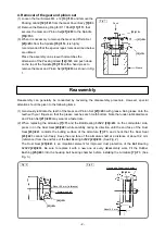
Hitachi G 10SS2(S) Скачать руководство пользователя страница 4

-3- 

 Fig. 4  

(3) Before inserting the Stator 

[9]<9>

 into the Housing 

[26]<25>

, correctly connect the internal wires of the 

Stator 

[9]<9>

 to each part without entangling as shown in Fig. 4. 

NOTE: • Be careful not to put the internal wire of the Carbon Brush [27]<26> between the 

Housing [26]<25> and the internal wires of the Stator [9]<9> when connecting the 

internal wires of the Stator [9]<9> or when connecting the Carbon Brush [27]<26>. 

• The internal wire (single wire) of the Stator [9]<9> is covered with a heat-shrinkable 

tube. Do not forcefully bend the internal wire of the Stator [9]<9> repeatedly and do 

not peel off the heat-shrinkable tube when mounting the Stator [9]<9> to the Housing 

[26]<25>. Otherwise, the internal wire may be disconnected. 

• Do not forcefully bend the stator terminal when inserting the stator terminal into the 

Pushing Button Switch [32]<31> and the tab terminal. Otherwise, the stator terminal 

may be broken. 


(1) When replacing the Gear Cover Ass’y 

[3]<3>

, lubricate the metal with the following mixed oil. 

Mixed oil: Mixture of Hitachi power tool grease No. 2 (Unilube No. 00) and turbine oil 
• Mixture ratio: 1:1 (weight ratio) 
• Volume: 0.5 cc 

(2) Generously rub 10 g of Shell GADUSS2V1003 grease onto the gear and pinion of the Gear Cover 

Ass'y 

[3]<3>


• Seal Lock Screw (W/Washer) M4 x 12 

[13]<13>

 -------- 1.8 ± 0.5 N•m (18 ± 4 kgf•cm, 1.3 ± 0.3 ft-lbs.) 

• Tapping Screw (W/Flange) D4 

[41][36]<40><35>

 ------ 2.0 ± 0.5 N•m (20 ± 5 kgf•cm, 1.5 ± 0.4 ft-lbs.) 

• Machine Screw (W/Sp. Washer) M5 x 16 

[16]<16>

 ---- 3.4 ± 0.7 N•m (35 ± 7 kgf•cm, 2.5 ± 0.5 ft-lbs.) 

• Special Nut M6 

[4]<4>

 ----------------------------------------- 4.9 ± 1.0 N•m (50 ± 10 kgf•cm, 3.6 ± 0.7 ft-lbs.) 

• Tapping Screw D3 x 8 

[29]<28>

 ----------------------------- 0.6 ± 0.1 N•m (6.2 ± 1.2 kgf•cm, 0.4 ± 0.07 ft-lbs.) 

Lubrication point and type of lubricant 

Tightening torque 

Connect the internal wire to the 
Pushing Button Switch

 [32]<31>

White 

White 

Connect the internal wires to 
the Tab Terminal

 [28]<27>

Connect the internal wire to the 
Pushing Button Switch

 [32]<31>

[26]<25>


[9]<9>


Содержание G 10SS2(S)

Страница 1: ...5 mm 4 1 2 G 12STA S G 12STX 125 mm 5 G 13STA S G REPAIR GUIDE 1 1 Precautions on disassembly and reassembly 1 STANDARD REPAIR TIME UNIT SCHEDULES 6 CONTENTS Page G LIST Nos G 10SS2 S F233 G 12STA S F235 G 12STX F242 G 13STA S F237 Feb 2016 Overseas Sales Division ...

Страница 2: ...en remove the Bearing Holder 6 6 6 Remove the four internal wires connected to the Tab Terminal 28 27 and Pushing Button Switch 32 31 from the Stator 9 9 7 Remove the Fan Guide 8 8 and Stator 9 9 from the Housing 26 25 NOTE If you have any trouble in removing the Stator 9 9 heat the Housing 26 25 to about 60 C for easier removal The internal wire single wire of the Stator 9 9 is covered with a hea...

Страница 3: ...h grease Rub grease onto the teeth with your fingers so that the grease reaches each tooth bottom Note that under lubricated Gear and Pinion Set 21 20 may wear at a faster rate 2 When replacing the Armature 7 7 and the Ball Bearing 626ZZ 24 23 on the commutator side press in on the Dust Seal 23 22 while carefully noting its direction until the end face of the Dust Seal 23 22 contacts the butting s...

Страница 4: ...h 32 31 and the tab terminal Otherwise the stator terminal may be broken 1 When replacing the Gear Cover Ass y 3 3 lubricate the metal with the following mixed oil Mixed oil Mixture of Hitachi power tool grease No 2 Unilube No 00 and turbine oil Mixture ratio 1 1 weight ratio Volume 0 5 cc 2 Generously rub 10 g of Shell GADUSS2V1003 grease onto the gear and pinion of the Gear Cover Ass y 3 3 Seal ...

Страница 5: ... with no abnormalities 230 V 2 500 VAC minute with no abnormalities 110 V After no load operation for 30 minutes the no load current values should be as follows Voltage 110 V 230 V Current max 2 8 A 1 1 A Insulation test No load current value Fig 5 Wiring diagram Stator 9 9 Pushing Button Switch 32 31 Black Brown Blue Stator 9 9 Black Black Red 1 C1 White Black 2 C2 Varistor A Ass y 43 42 Controll...

Страница 6: ...e Bar Slide Switch Knob Armature Ball Bearing 608SS Bearing Cover Dust Seal Ball Bearing 626ZZ Rubber Bushing Gear Cover Ass y Pushing Button Lock Pin Packing Gland Spindle Gear and Pinion Set Work Flow Pushing Button Switch Tail Cover Cord Cord Armor Varistor A Ass y Wheel Guard Ass y STANDARD REPAIR TIME UNIT SCHEDULES ...

Отзывы: