


Oper
ating Instr
uctions
4-3
16
T
our of the Remote Control
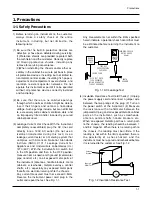
How to handle the remote control
Operate the remote control within the following area, in a straight line from the signal
detecting eye of the player and an angle of 30
°.
30
Approx. 7m(Approx. 23 feet)
30
30
30
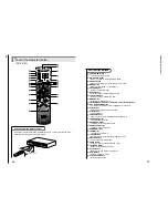
— DV-P313U —
17
DVD POWER Button
• Turns the player on and off.
NUMBER Buttons
REPEAT Button
• Allows you to repeat play a title, chapter, track, or disc.
A-B REPEAT Button
• Marks a segment to repeat between A and B.
SETUP Button
• Brings up the DVD player's Setup menu.
MODE Button
• Allows you to program a specific order.
SEARCH Buttons
• Allows you to search forward/backward through a disc.
STOP Button
• To stop playback.
SKIP Buttons
• Skip the, Chapter, or Track.
MENU Button
• Brings up the Menu on a disc.
TOP MENU Button
• Brings up the Top Menu on a disc.
ENTER/DIRECTION Button (UP/DOWN or LEFT/RIGHT Button)
STEP Button
• Advances playback one frame at a time.
AUDIO Button
• Accesses various audio functions on a disc.
OPEN/CLOSE Button
• To open or close the disc tray.
3D SOUND Button
• To activate the 3D sound.
ZOOM Button
• To magnify part of picture.
CLEAR Button
• Removes menus or status displays from the screen.
BOOKMARK Button
• To rapidly return to a location of disc.
PLAY/PAUSE Button
• Begin/Pause disc play.
RETURN Button
• Returns to a previous menu.
DISPLAY Button
• Displays the current disc mode.
ANGLE Button
• Accesses various camera angles on a disc.
SUBTITLE Button
• Accesses various subtitles on a disc.
DVD Function Buttons
Содержание DV-P313U
Страница 9: ...Product Specification 3 2 MEMO ...
Страница 19: ...5 6 Disassembly and Reaasembly 5 2 PCB Location Fig 5 6 PCB Location ...
Страница 34: ...8 1 8 Exploded View 8 1 Cabinet Assembly 8 2 Deck Assembly Page 8 2 8 3 ...
Страница 35: ...Exploded Views 8 2 8 1 Cabinet Assembly 104 101 001 MAIN P C B 002 JACK P C B 102 109 106 108 108 CN1B 103 105 ...
Страница 36: ...Exploded Views 8 3 8 2 Deck Assembly 107 H220 H106 H207 H200 H210 ...
Страница 37: ...Exploded Views 8 4 MEMO ...
Страница 41: ...Block Diagram 10 2 MEMO ...
Страница 42: ...11 1 11 PCB Diagrams 11 2 11 3 11 4 11 4 11 1 Main 11 2 Jack 11 3 Deck 11 4 Housing ...
Страница 43: ...PCB Diagrams 11 2 11 1 Main COMPONENT SOLDER SIDE ...
Страница 44: ...PCB Diagrams 11 3 11 2 Jack ...
Страница 45: ...PCB Diagrams 11 4 11 3 Deck 11 4 Housing ...
Страница 46: ...12 1 12 Wiring Diagram ...
Страница 47: ...Wiring Diagram 12 2 MEMO ...
Страница 49: ...Schematic Diagrams 13 2 13 1 Power ...
Страница 50: ...Schematic Diagrams 13 3 13 2 AV Decoder Main Micom Key KEY ...
Страница 51: ...Schematic Diagrams 13 4 13 3 Servo ...
Страница 52: ...Schematic Diagrams 13 5 OPTION 13 4 Video ...
Страница 53: ...Schematic Diagrams 13 6 OPTION OPTION 13 5 Audio ...
Страница 54: ...Schematic Diagrams 13 7 OPTION OPTION 13 6 Front Micom VFD Display ...
Страница 55: ...Schematic Diagrams 13 8 HOUSING PCB 13 7 Deck ...


