


--- 17 ---
(c) Set the assembly reassembled in step (b) to Housing (B) [32] and secure it with the seven Tapping Screws
(W/Flange) D3 x 16 (Black) [29].
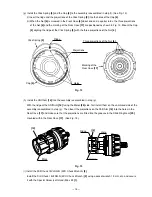
(d) Verify proper operation of the Cap [4].
When the assembly procedure up to step (c) is completed, ensure that the number "1" on the Cap [4] and
the drill mark " " are in alignment with the triangle mark on Housing (A). (B) Set [32]. If the Cap [4]
turns loosely, correctly re-install the Click Spring [5] as it is improperly installed. If the number "1" on the
Cap [4] or the drill mark " " cannot reach the triangle mark on Housing (A). (B) Set [32], correctly re-
install the Cap [4] referring to step (3) (c), as it is improperly installed.
(5) Other precautions in reassembly
(a) When the assembly procedure is completed, make sure that the turning direction of the Drill Chuck
13VLRG-N (W/O Chuck Wrench) [2] corresponds to the position of the Pushing Button [36]. When the
Pushing Button [36] is pressed from the (R)-marked side, the Drill Chuck 13VLRG-N (W/O Chuck Wrench)
[2] should turn clockwise when viewed from the rear (opposite side of the Drill Chuck 13VLRG-N (W/O
Chuck Wrench) [2]). Also make sure that the turning speed of the Drill Chuck 13VLRG-N (W/O Chuck
Wrench) [2] switches between "HIGH" and "LOW" by switching over the Shift Knob [38]. Switch on and off
the Model DS 12DVB using the battery. Then turn the Drill Chuck 13VLRG-N (W/O Chuck Wrench) [2] by
hand in forward and reverse direction to check that the spindle lock properly works in either direction within
a half rotation. Make sure that the run-out of the Drill Chuck 13VLRG-N (W/O Chuck Wrench) [2] holding a
12 mm dia. test bar is below 0.8 mm at a distance of 110 mm from the chuck end.
(b) The tightening torque of each screw is given below.
Special Screw (Left Hand) M6 x 23 [1]
: 2.9 --- 3.9 N
•
m ( 30 --- 40 kgf
•
cm, 26.1 --- 34.8 in-lbs.)
Drill Chuck 13VLRG-N (W/O Chuck Wrench) [2] : 17.7 --- 21.6 N
•
m (180 --- 220 kgf
•
cm, 156 --- 191 in-lbs.)
Screw Set D3 x 12 (4 pcs.) [18]
: 0.6 --- 1.0 N
•
m ( 6 --- 10 kgf
•
cm, 5.2 --- 8.7 in-lbs.)
Machine Screw (W/Sp. Washer) M4 x 6 or 8 [31] : 1.1 --- 1.9 N
•
m ( 11 --- 19 kgf
•
cm, 9.5 --- 16.5 in-lbs.)
Tapping Screw (W/Flange) D3 x 16 (Black) [29] : 1.1 --- 1.9 N
•
m ( 11 --- 19 kgf
•
cm, 9.5 --- 16.5 in-lbs.)
10-2. Precautions in Disassembly and Reassembly of Battery Charger
Please refer to the Technical Data and Service Manual for precautions in disassembly and reassembly of the
Battery Charger UC 14YF2 or UC 24YFA.