


-28-
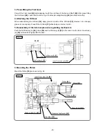
Fig. 28
x
Wiring of reversing switch
Fig. 29
x
Wiring of speed control switch
B. Additional wiring work
General internal wiring can be performed by referring to the wiring diagrams in Section 9 above. The
following are special instructions on switch connections.
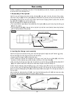
(1) Wiring of the reversing switch
Insert the lead wire (black) protruding from the stator into terminal (4) of the reversing switch, and then
insert the lead wire (white) into terminal (3) as shown in Fig. 28. Insert the lead wire (brown) protruding
from the carbon brush or choke coil into terminal (2), and then insert the lead wire (blue) into terminal (1).
After inserting the wires, slightly pull each lead wire to confirm that the lead wires do not come off. To
disconnect the lead wires, insert a small flat-blade screwdriver into the openings near the terminals and
pull out the lead wires.
(2) Wiring of the speed control switch
Insert each cord into terminals (1 ) and (2 ) of the speed control switch as shown in Fig. 29, and then
tighten the screw (tightening torque: 0.6 ± 0.2 N
x
m (6 ± 2 kgf
x
cm, 5.2 ± 1.7 in-lbs.)).
Insert the lead wire (gray) protruding from the stator into terminal (M1), and then insert the lead wire
(red) into terminal (M2). Insert each lead wire (white) protruding from the noise suppressor into
terminals (C1) and (C2). After inserting the wires, slightly pull each lead wire to confirm that the lead
wires do not come off. To disconnect the lead wires, insert a small flat-blade screwdriver into the
openings near the terminals and pull out the lead wires.
Содержание DH 22PH
Страница 21: ... 18 Fig 12 x Dust collector B structure ...