


--- 12 ---
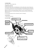
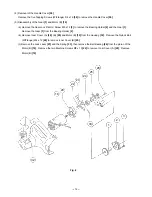
Fig. 4
19
20
22
23
24
25
26
33
1
2
3
32
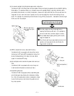
(4) Removal of the Handle Cover [55]
Remove the five Tapping Screws (W/Flange) D4 x 16 [56] to remove the Handle Cover [55].
(5) Disassembly of the Gear [1] and Motor (B) [19]
(a) Remove the Seal Lock Flat Hd. Screw M5 x 12 [3] to remove the Bearing Holder [2] and the Gear [1].
Remove the Gear [1] from the Bearing Holder [2].
(b) Remove Inner Cover (A) [20], (B) [25] and Motor (B) [19] from the Housing [32]. Remove the Nylock Bolt
(W/Flange) M4 x 12 [26] to remove Inner Cover (B) [25].
(c) Remove the Lock Lever [23] and the Spring [33], then remove the Ball Bearing [24] from the pinion of the
Motor (B) [19]. Remove the two Machine Screws M5 x 10 [22] to remove Inner Cover (A) [20]. Remove
Motor (B) [19].
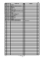
Содержание C 6DC
Страница 23: ... 20 Assembly Diagram for C 6DC ...