6
42PD9700C/U & 55PD9700C/U
4. Component names
[Main unit]
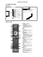
Control panel
• The main power switch is located on the lower surface.
Main power switch
Remote Control
Receiver
Indicating Lamp
SD Memory Card Slot
Sub Power button
Channel UP/ button
Channel DOWN/ button
Volume UP
/ button
Volume DOWN
/ button
Input Select /OK button
Menu / Return button
OK
P
P
SD MEMO RY
CARD
PUSH-EJECT
PH35814
[Remote control]
Sub Power
Function Select (TV/DVD/SAT)
Press this button to select function mode
indicating LED lamp.
Normally, select “TV”.
Input Select/DVD Control/Photo Input Control
Press this button to change input mode.
In addition, you can use these buttons while
operating the selected brand of DVD player or
Photo Input function.
Menu
Cursor
OK
Sound Mode
Sound mode can be changed each time pressed
in the following sequence. Movie→Music→
Speech→Favourite
CHI/II
This is exclusively for TV audio A2/NICAM mode.
Volume Up/Down
Programme Select
Press these buttons to select a TV program
directly.
Freeze/Multi Mode [Hold]
Press this button to change the picture to freeze
mode. Press it again to return to normal picture.
In addition, during multi-picture mode, each time
press this button, the picture is changed to 2, 4,
and 12 multi mode. (Also, it holds the page in
text mode.)
[Colour (Red, Green, Yellow, Blue)]
[Index]
Time [Cancel]
Pressing this button can indicate the time by On-
Screen display when receiving a TV programme
on the screen.
TV/Text [TV Text]
This switches between the TV mode and the
Teletext mode.
Zoom [Text TV+Text]
Press this button to change picture size.
Recall
Pressing this button shows the input signal
status.
Return
You can use this to return to the previous menu.
Picture Mode
Picture mode can be changed each time pressed
in the following sequence. Dynamic→Natural→
Cinema
Channel Up/Down
Mute
Multi Picture
Press this button to change the picture to multi-
picture mode. Press it again to return to normal
picture.
Photo Input (Photo/Rotate/Slide Show)
These buttons are to display and control the
pictures from digital still camera or USB card
reader.
Swivel
(with Desktop Stand)
This function is to rotate TV. Select the degree
of rotation with cursor key.
Содержание 42PD9700C
Страница 58: ...SM 011 POWER BOARD CIRCUIT SHEET 1 ...
Страница 59: ...SM 011 POWER BOARD CIRCUIT SHEET 2 ...
Страница 60: ...SM 011 POWER BOARD CIRCUIT SHEET 3 ...
Страница 61: ...SM 011 POWER BOARD CIRCUIT SHEET 4 ...
Страница 62: ...SM 011 POWER BOARD CIRCUIT SHEET 5 ...
Страница 63: ...SM 011 MAIN BOARD CIRCUIT SHEET 1 ...
Страница 64: ...SM 011 MAIN BOARD CIRCUIT SHEET 2 A WAKE UP MAIN 5 ...
Страница 65: ...SM 011 MAIN BOARD CIRCUIT SHEET 3 ...
Страница 66: ...SM 011 MAIN BOARD CIRCUIT SHEET 4 ...
Страница 67: ...SM 011 MAIN BOARD CIRCUIT SHEET 5 MAIN 2 ...
Страница 69: ...SM 011 SUB POWER BOARD CIRCUIT ...
Страница 70: ...SM 011 CONTROL BOARD CIRCUIT ...
Страница 71: ...SM 011 SOUND BOARD CIRCUIT ...
Страница 74: ...SM 011 FC BOARD CIRCUIT SHEET 3 ...
Страница 75: ...SM 011 FC BOARD CIRCUIT SHEET 4 about 7mA It is 0 4V at 22V to in press it ...
Страница 76: ...SM 011 FC BOARD CIRCUIT SHEET 5 Female BM VIDEO change To IC202ARGB AMP ...
Страница 78: ...SM 011 FC BOARD CIRCUIT SHEET 7 A B work C D work A B work C D work ...
Страница 79: ...SM 011 FC BOARD CIRCUIT SHEET 8 ...
Страница 80: ...SM 011 FC BOARD CIRCUIT SHEET 9 MAIN µ com ...
Страница 81: ...SM 011 POWER BOARD ...
Страница 82: ...SM 011 MAIN BOARD COMPONENT TOP SIDE ...
Страница 83: ...SM 011 MAIN BOARD SOLDER BOTTOM SIDE ...
Страница 85: ...SM 011 FC BOARD SOLDER BOTTOM SIDE COMPONENT TOP SIDE ...
Страница 90: ...SM 011 WIRING ASSEMBLY DIAGRAM 1 ...
Страница 91: ...SM 011 WIRING ASSEMBLY DIAGRAM 2 ...
Страница 92: ...SM 011 WIRING ASSEMBLY DIAGRAM 3 ...
Страница 93: ...SM 011 ASSEMBLY DIAGRAM ...
Страница 95: ...THE UPDATED PARTS LIST FOR THIS MODEL IS AVAILABLE ON ESTA ...


