38
42PD9700C/U & 55PD9700C/U
7. Troubleshooting
How to get to Burn-in mode
This mode displays the test patterns of some single color raster in turn. These signals are from built-in gener
-
ator of panel. So it can be presumed that maybe the panel has some trouble when the screen of Burn-in
mode is abnormal.
Using the R-side control buttons with the set turned off (standby) can activate this mode.
Press the SUB-POWER( ) button, INPUT SELECT( ) button and VOLUME DOWN( ) button at the
same time, and hold for more than 5 seconds.
The set turns on with single color raster and the OSD of [BURN IN: ON].
To escape from this mode, press the SUB-POWER( ) button, INPUT SELECT( ) button and button at
the same time, and hold for more than 5 seconds. Burn-in mode will be released.
How to recover the remote and R-side control key function
If remote and R-side control key cannot operate after miss set special function by front keys, these functions
can recover by below method.
Press the SUB-POWER( ) button, INPUT SELECT( ) button and button at the same time, and hold for
more than 5 seconds.
The set turns on the service menu mode.
Select No.721 and No.722 then each data set from [0] to [1].
Or
Press the SUB-POWER( ) button and button at the same time, and hold for more than 5 seconds
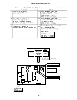
How to check method of the use accumulation time for panel.
Select No.894 of Service Adjustment Menu.
Содержание 42PD9700C
Страница 58: ...SM 011 POWER BOARD CIRCUIT SHEET 1 ...
Страница 59: ...SM 011 POWER BOARD CIRCUIT SHEET 2 ...
Страница 60: ...SM 011 POWER BOARD CIRCUIT SHEET 3 ...
Страница 61: ...SM 011 POWER BOARD CIRCUIT SHEET 4 ...
Страница 62: ...SM 011 POWER BOARD CIRCUIT SHEET 5 ...
Страница 63: ...SM 011 MAIN BOARD CIRCUIT SHEET 1 ...
Страница 64: ...SM 011 MAIN BOARD CIRCUIT SHEET 2 A WAKE UP MAIN 5 ...
Страница 65: ...SM 011 MAIN BOARD CIRCUIT SHEET 3 ...
Страница 66: ...SM 011 MAIN BOARD CIRCUIT SHEET 4 ...
Страница 67: ...SM 011 MAIN BOARD CIRCUIT SHEET 5 MAIN 2 ...
Страница 69: ...SM 011 SUB POWER BOARD CIRCUIT ...
Страница 70: ...SM 011 CONTROL BOARD CIRCUIT ...
Страница 71: ...SM 011 SOUND BOARD CIRCUIT ...
Страница 74: ...SM 011 FC BOARD CIRCUIT SHEET 3 ...
Страница 75: ...SM 011 FC BOARD CIRCUIT SHEET 4 about 7mA It is 0 4V at 22V to in press it ...
Страница 76: ...SM 011 FC BOARD CIRCUIT SHEET 5 Female BM VIDEO change To IC202ARGB AMP ...
Страница 78: ...SM 011 FC BOARD CIRCUIT SHEET 7 A B work C D work A B work C D work ...
Страница 79: ...SM 011 FC BOARD CIRCUIT SHEET 8 ...
Страница 80: ...SM 011 FC BOARD CIRCUIT SHEET 9 MAIN µ com ...
Страница 81: ...SM 011 POWER BOARD ...
Страница 82: ...SM 011 MAIN BOARD COMPONENT TOP SIDE ...
Страница 83: ...SM 011 MAIN BOARD SOLDER BOTTOM SIDE ...
Страница 85: ...SM 011 FC BOARD SOLDER BOTTOM SIDE COMPONENT TOP SIDE ...
Страница 90: ...SM 011 WIRING ASSEMBLY DIAGRAM 1 ...
Страница 91: ...SM 011 WIRING ASSEMBLY DIAGRAM 2 ...
Страница 92: ...SM 011 WIRING ASSEMBLY DIAGRAM 3 ...
Страница 93: ...SM 011 ASSEMBLY DIAGRAM ...
Страница 95: ...THE UPDATED PARTS LIST FOR THIS MODEL IS AVAILABLE ON ESTA ...


