


-244-
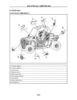
ELECTRICAL COMPONENTS
- 244 -
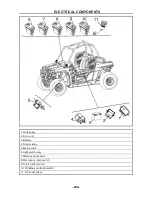
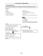
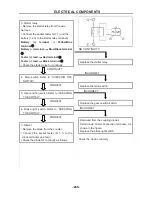
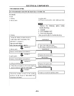
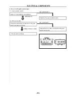
Procedure
Check:
1. Battery
2. Starter motor
3. Starter relay
4. Main switch
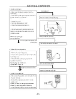
1. Battery
• Check the battery condition. Refer to
“CHECKING AND CHARGING THE
BATTERY” in chapter 3.
Open-circuit voltage
12.8 V or more at 20 °C (68 °F)
CORRECT
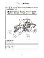
2. Starter motor
• Connect the battery (+) terminal
①
and
starter motor cable
②
using a jumper lead
③
• Check the operation of the starter motor.
TURNS
5. Gear position switch
6. Brake light switch
7. Diode 1
8. Wiring connection (the entire starting system)
NOTE
:
• Remove the following part(s) before
troubleshooting:
1. Console
2. Front frame
3. Front fender
• Use the following special tool(s) fo
r
troubleshooting.
INCORRECT
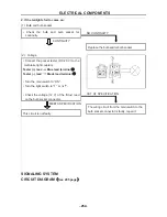
WARNING
:
• A wire that is used as a jumper lead must
have the equivalent capacity or more as that
of the battery lead, otherwise the j
umper
lead may burn.
• This check is likely to produce sparks, so
be sure that no flammable gas or fluid is in
the vicinity.
DOSE NOT TURN
Repair or replace the starter motor.
Small testers and battery and (12V) and start
relay terminal connection
Check continuity of the start relay
• Clean the battery terminals.
• Recharge or replace the battery.
TROUBLESHOOTING
IF THE STARTER MOTOR FAILS TO OPERATE:
ELECTRICAL COMPONENTS
- 245 -
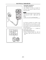
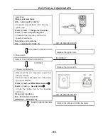
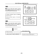
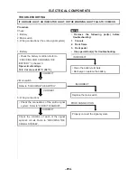
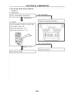
3. Starter relay
• Remove the starter relay from the wire
harness.
• Connect the pocket tester (
Ω
× 1) and the
battery (12 V) to the starter relay terminals.
Battery (+) terminal
Yellow/Blue
terminal
①
Battery (–) terminal
Blue/Black terminal
②
Tester (+) lead
Red terminal
③
Tester (–) lead
Black terminal
④
• Check the starter relay for continuity.
CONTINUITY
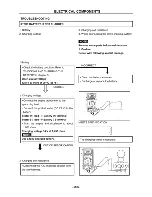
4. Main switch Refer to “CHECKING THE
SWITCH”.
CORRECT
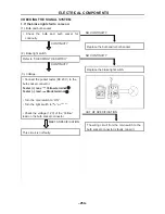
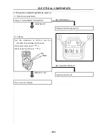
5. Gear position switch Refer to “CHECKING
THE SWITCH”.
CORRECT
6. Brake light switch Refer to “CHECKING
THE SWITCH”.
CORRECT
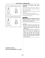
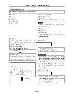
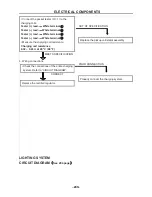
7. Diode 1
• Remove the diode from the coupler
• Connect the pocket tester (
Ω
× 1) to the
diode terminals as shown.
• Check the diode for continuity as follows
NO CONTINUITY
Replace the starter relay.
INCORRECT
Replace the main switch.
INCORRECT
Replace the gear position switch.
INCORRECT
Removed from the coupling diodes
Small diode Tester connection terminals, As
shown in the figure
Replace the brake light switch.
Check the diode continuity
Содержание HS200UTV
Страница 3: ......
Страница 15: ......
Страница 94: ... 79 SPECIFICATIONS 79 HYDROGRAPHIC CHART Hydrographic chart Pressure ...
Страница 95: ... 80 SPECIFICATIONS 80 LUBRICATION OIL WAY LUBRICATION OIL WAY Pressure splashing oil ...
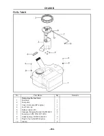
Страница 248: ... 233 CHASSIS 233 Fuel tank cap Remove the fuel tank cap by turning it counterclockwise ...
Страница 263: ... 248 ...
Страница 304: ... 289 ...
Страница 305: ... 290 ...
Страница 306: ... 291 ...
Страница 307: ... 292 ...
Страница 308: ... 293 ...
Страница 309: ... 294 ...
Страница 310: ... 295 ...
Страница 311: ... 296 ...
Страница 312: ...TM HISUN MOTORS 310 East University Dr McKinney Texas 75069 PH 972 446 0760 TF 877 838 6188 hisunmotors com ...


