Installation Instructions
ML19G User Manual, January 2015
7
Step 2: Bench-test Configuration
Make sure everything works before installing into the production environment�
TIP!
If using a KVM extender, please refer to the installation instructions included
with the KVM extender module� It is particularly important to bench-test the full
configuration prior to final installation� This will help to identify and troubleshoot
any system issues while configuration changes may still be easily made�
Install Cable Connections
All monitors are shipped with both a 6 ft� (1�8 m) VGA video cable and 6 ft� (1�8 m) power cable,
unless longer cables were ordered in their place� DC models are shipped with a bench test
power supply� If you ordered a touch screen monitor, you also received a 6 ft� (1�8 m) USB
cable, unless a longer cable was ordered in its place� Serial (RS-232) cables may be ordered
separately�
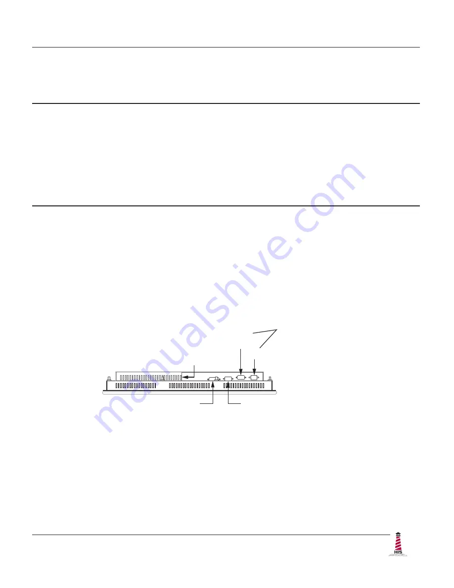
The cable ports are located on the rear of the monitor� Refer to the following diagram and
instructions to connect power, video, and touch screen (if applicable) to your monitor�
Video Connection
The HIS-ML19 supports analog and digital video�
Analog VGA Video Connection
Connect one end of the VGA video cable to the HD-15 input port on the rear of the
monitor� Connect the other end to the analog video output port on the host computer�
Digital DVI Video Connection
Connect one end of the DVI video cable to the DVI-D input port on the rear of the
monitor� Connect the other end to the digital video output port on the host computer�
DIGITAL VIDEO
USB
(for Touch Screen option)
SERIAL
(RS-232)
POWER INPUT
ANALOG VIDEO


