System 2000 AUTO TEMP
8
for an alternating crop. Then when you return to the original crop you could simply
restore the level you had saved. This will reprogram the stages back to the original
settings. Note: Saving a level completely erases the level which was previously saved for
that number, so be sure before you save. The system has accommodations for two levels.
6.2.6.
Calibrating the Temperature Sensors
In any Given installation it is usually necessary to calibrate at least one of the seven
sensors. With a program located in the Program Features the Auto Temp makes this an
easy task. All that is needed to calibrate sensors is a stable building with no fans or
heaters running, and a trusted thermometer. Use the thermometer to check temperature
at the sensor locations. Then use the Select feature arrow keys to find Calibrate Sensors.
Answer Yes and the controller will ask for new temperature for Sensor 1, use the change
setting arrows to enter the correct temperature, then answer in the same manner for
Sensor 2, and so on.
6.2.7.
Artificial Light
The Auto Temp Controller has a way to control artificial lighting based on a 24 hour
time clock. There is a connection in the controller labeled "Artificial Light", in and out.
An external relay or contactor must be used to control the lighting as the relay in the
Auto Temp is not heavy enough. When programming this feature, the operator is
prompted for
Number of Cycles
(up to two),
Time on
and
Time off.
The operator can use
up to two different light cycles in every day.
6.2.8.
Feed Control
This feature can be used for feeders, or any other device that needs to run on a timed
basis. Feed Control allows you to set up the device to operate up to Four times a day.
The controller will prompt you for number of cycles (up to two), then begin cycle time,
and end cycle time for each. When Feed Control is used, it will use Stage 11, and Stage
12 for operation.
6.2.9.
Viewing All Sensors
It is possible to view all 7 sensors on 2 separate screens with the System 2000. To see
the temperatures sensed by the sensors, go into programming features, and continue
until you see a screen with S-1... S-2... and so on. This screen, and the next shows the
actual sensor readings. This allows you to detect a problem with your setup, or the
sensor itself. The temperatures shown will update every 4 seconds while they are being
displayed.
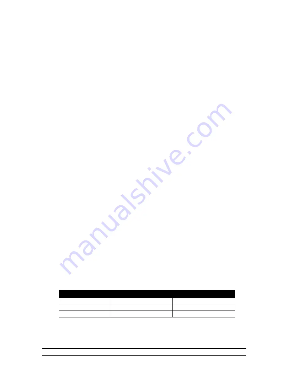
Recommended Wire Gauge for LOW VOLTAGE hookup.
Component
HHI Wiring Part No. Recommended Wire
Sensor
1502-2427
18/2 Shielded Cable
Hall Effect Devices
1502-2427
18/2 Shielded Cable
PVR-H
1503-1508
18/3 Cable SJT


