background image

ADVERTENCIA:

Lea y siga estas instrucciones cuidadosamente y tenga en cuenta todas las advertencias que se muestran a lo 

largo

.

©2020 Hinkley Lighting, Inc. 

|

 hinkley.com 

|


01

TABLA DE CONTENIDO

02

03

03

04

05

05

06

08

09

INSTRUCCIONES GENERALES DE INSTALACIÓN 

Y FUNCIONAMIENTO

PRECAUCIONES IMPORTANTES DE SEGURIDAD

HERRAMIENTAS Y MATERIALES REQUERIDOS

DESEMBALAJE SU VENTILADOR

PREPARACIÓN

INSTALACIÓN DEL SOPORTE COLGANTE

COLGANDO EL VENTILADOR

CONEXIONES ELÉCTRICAS

TERMINANDO LA INSTALACIÓN

INSTALACIÓN DE LAS CUCHILLAS

10

10

11

12

13

14

14

15

15

15

INSTALACIÓN DE LA PLACA DE MONTAJE

INSTALACIÓN DE LAS BOMBILLAS LED Y LAS CORTINAS DE VIDRIO

INSTALACIÓN DEL CONTROL DE PARED

OPERACIÓN

CUIDADO Y LIMPIEZA

SOLUCIÓN DE PROBLEMAS

GUÍA ENERGÉTICA

ESPECIFICACIONES

INTELIGENTE POR BOND

Содержание SAWYER

Страница 1: ...36 SAWYER CEILING FAN INSTRUCTION MANUAL INDOOR OUTDOOR LED FAN LED WET ...

Страница 2: ... installation and operation of this fan It has been designed to make the installation process as easy as possible If you are unfamiliar or uncomfortable with wiring please contact a qualified electrician If you need additional assistance or have any questions please reach out to us For warranty information visit hinkley com SERVICE HINKLEY COM 800 HINKLEY LET S SEE THAT HINKLEY STYLE HINKLEY HINKL...

Страница 3: ...TY PRECAUTIONS 03 TOOLS MATERIALS REQUIRED 04 UNPACKING YOUR FAN 05 PREPARATION 05 INSTALLING THE HANGING BRACKET 06 HANGING THE FAN 08 ELECTRICAL CONNECTIONS FINISHING THE INSTALLATION 09 INSTALLING THE BLADES 10 INSTALLING THE MONTING PLATE 10 11 INSTALLING THE LED BULBS AND GLASS SHADES 12 INSTALLING THE WALL CONTROL 13 14 14 OPERATION CARE AND CLEANING TROUBLESHOOTING 15 15 15 ENERGY GUIDE SPE...

Страница 4: ...not allow rotating fan blades to come in contact with any object Blades should be at least 7 feet from floor Blades should be attached after motor housing is hung and in place Fan motor housing should be kept in the carton until ready to be installed to protect its finish If you are installing more than one ceiling fan make sure that you do not mix fan blade sets as each blade is part of a weighted ...

Страница 5: ...03 Disconnect power by removing fuse or turning off circuit breaker before installing the fan and or optional lighting Support directly from building structure To reduce the risk of fire electric shock or personal injury mount to outlet box marked acceptable for fan support and use mounting screws provided with the outlet box Most outlet boxes commonly used for the support of lighting fixtures are no...

Страница 6: ...nopy and Trim Ring C Ring 4 5 6 1 6 2 12 downrod assembly 24 downrod Yoke Cover 13 14 15 BL902928Fxx CA9000752Fxx YC902928Fxx DR94012Fxx x 990024Fxx 7 8 1 8 2 9 10 11 12 13 14 15 16 Fan Housing with Motor 12 chain Set w couplers 24 chain Set w couplers Adapter Plate Glass Shades Bottom Cover Hardware Bag Bracket Mounting Hardware wood screws screws lock washers star washers flat washers wire nuts B...

Страница 7: ...ce with National and Local Electrical Codes and the ceiling fan must be grounded as a precaution against possible electric shock 1 2 3 4 Locate ceiling joist where fan is to be mounted being sure location agrees with the requirements in the minimum clearance section of this guide Wood joists must be sound and of adequate size to support 35 pounds See page 2 items 3 and 4 If not already present mou...

Страница 8: ...es come out facing upward Loosen the two security set screws and remove the downrod pin and retaining clip from the coupling on top of the motor assembly Fig 2 Carefully feed the electrical lead wires and safety cable from the fan through the downrod Thread downrod into coupler until holes align Insert downrod pin through holes in mounting collar and downrod clip cotter pin through small hole in e...

Страница 9: ...ons Slide canopy up and fasten to hanger bracket with 4 screws provided Fig 3 Ground Wire Hook up 3 Wires Downrod Cross Pin Hanger Ball Set Screw Top of Fan Body Yoke Cover Canopy Trim Ring C Ring Safety Cable Fig 4 Attach the wood screw and the flat washer to the ceiling joist as shown do not fully tighten Slide the cable clamp onto the safety cable from the fan Loop the safety cable around the wo...

Страница 10: ... the GRAY receiver wire Connect the RED fan neutral wire to the RED receiver neutral wire Connect the WHITE fan neutral wire to the WHITE receiver neutral wire Connect the BLUE fan neutral wire to the BLUE receiver neutral wire 3 Connect the wiring from the ceiling to the receiver unit Use the 2 wire bundle on the receiver Secure with supplied wire nuts Connect the BLACK building supply wire to th...

Страница 11: ...til the canopy and trim ring are snug Loosen the buckles at one end of the chain and attach to the chain support loops of the fixture Loosen the remaining buckles of the chain ends and install the chain to the C Ring on the fan downrod Slide the C Ring up the downrod until the chains are taunt Secure the C Ring into position on the downrod by securing the two set screws WARNING Make sure the hook ...

Страница 12: ...y holes on the rubber gasket and adapter plate over the 2 screws previously loosened turn the adapter plate until it locks in place at the narrow section of the key holes Secure by tightening the 2 screws previously loosened and the one previously removed Raise the bottom cover against the adapter plate with 2 screws until snug Restore power is ready for operation Fig 2 Fig 1 Screws Screws 1 2 3 M...

Страница 13: ...BS AND GLASS SHADES 1 2 3 Fig 3 NOTE Be sure the power is off before installing Install 8 x 4 W LED bulbs included Raise the glass shade against the light holder and turn clockwise until snug DO NOT OVERTIGHTEN Restore power is ready for operation Glass Shades Blubs ...

Страница 14: ...er unit Connect one BLACK wire from the wall to one BLACK wire labeled TO FAN from the wall transmitter Connect the other BLACK wire labeled TO POWER SUPPLY from the transmitter to the remaining BLACK wire from the wall A C supply source Connect the green ground wire form the switch to the ground wire on the wall outlet box Install the wall transmitter on the existing wall outlet box using the scr...

Страница 15: ... fan is running suggested speed IV Light button This button is to control optional light Switch the D and ON dip switch on the front of transmitter to decide the light in ON OFF or Dimmable condition SET code setting button Follow the below steps to use the set button Fig 1 ON OFF Slide button Power switch Fig 2 Signal light Fig 2 Pairing Process With the fan s power off restore power to the fan Pr...

Страница 16: ... 5 Check that the canopy is firmly attached to hanging bracket and not vibrating against ceiling 1 Check that all blades are firmly screwed into blade arms Check that all blade arms are firmly secure to the motor 2 Check to make sure that light kit if present is firmly attached to switch housing and that all glassware and shades are fastened properly Wobble can also result from even the smallest devia...

Страница 17: ...PTIONS SOLD SEPARATELY https bondhome io app n addition to the included wall control you can control your Hinkley fan through the Bond app using the smart technology accessory controls SOLD SEPARATELY To use the app download it for free from the App Store or Google Play Open the app to create your account You can also login with your Facebook or Google account Next set up a WiFi connection You wil...

Страница 18: ...WITH CEILING FAN PRODUCTS THAT ENHANCE YOUR SPACE WITH COMFORT PURPOSE AND STYLE AS A FAMILY COMPANY WE ARE COMMITTED TO DESIGN PERFORMANCE AND QUALITY AND WHAT S IMPORTANT TO YOU IS PARAMOUNT TO US FOR A COMPLETE ASSORTMENT OF OUR PRODUCTS AND SOURCE BOOKS VISIT HINKLEY COM ...

Страница 19: ...GLOBAL HEADQUARTERS 33000 Pin Oak Parkway Avon Lake Ohio 44012 T 440 653 5500 F 440 653 5555 hinkley com ...

Страница 20: ...MANUAL DE INSTRUCCIONES PARA VENTILADORES DE TECHO 36 SAWYER VENTILADOR LED INTERIOR EXTERIOR LED WET ...

Страница 21: ...ado Si necesita asistencia adicional o tiene alguna pregunta comuníquese con nosotros Para obtener información sobre la garantía visite hinkley com SERVICE HINKLEY COM 800 HINKLEY VAMOS A ESE ESTILO HINKLEY HINKLEY HINKLEYSTYLE QUEREMOS QUE AMES A TU NUEVO VENTILADOR ASÍ QUE ESTAMOS AQUÍ SI TIENE UNA PREGUNTA NECESITA AYUDA O QUIERE HABLAR SOBRE NUESTROS PRODUCTOS ENVÍE SUGERENCIAS NUESTRO CAMINO ...

Страница 22: ...TANTES DE SEGURIDAD HERRAMIENTAS Y MATERIALES REQUERIDOS DESEMBALAJE SU VENTILADOR PREPARACIÓN INSTALACIÓN DEL SOPORTE COLGANTE COLGANDO EL VENTILADOR CONEXIONES ELÉCTRICAS TERMINANDO LA INSTALACIÓN INSTALACIÓN DE LAS CUCHILLAS 10 10 11 12 13 14 14 15 15 15 INSTALACIÓN DE LA PLACA DE MONTAJE INSTALACIÓN DE LAS BOMBILLAS LED Y LAS CORTINAS DE VIDRIO INSTALACIÓN DEL CONTROL DE PARED OPERACIÓN CUIDAD...

Страница 23: ... instalación no permita que las aspas del ventilador giratorio entren en contacto con ningún objeto Las cuchillas deben estar a un mínimo de 7 pies del piso Las cuchillas deben colocarse después de que la carcasa del motor esté colgada y colocada La carcasa del motor del ventilador debe mantenerse en la caja hasta que esté lista para ser instalada para proteger su acabado Si está instalando más de...

Страница 24: ...izadas para el soporte de accesorios de iluminación no son aceptables para el soporte del ventilador y pueden necesitar ser reemplazadas Consulte a un electricista calificado si tiene dudas No utilice un atenuador de luz incandescente No utilice este ventilador con ningún dispositivo de control de velocidad del ventilador de tipo transformador To reduce the risk of personal injury do not bend the ...

Страница 25: ...de seguridad arandelas en estrella arandelas planas tuercas para cables tornillos de la cuchilla al motor con arandelas de goma Junta de goma Kit de equilibrio Hardware del cable de seguridad tornillo para madera arandela plana XX ACABADO VENTILADOR Receptor incl 5 tuercas de alambre Control de pared con placa de pared de batería de 12 v placa frontal 2 juegos de tornillos de montaje y tornillos d...

Страница 26: ...ales y locales y el ventilador de techo debe estar conectado a tierra como medida de precaución contra posibles descargas eléctricas 1 2 3 4 Ubique la viga del techo donde se instalará el ventilador asegurándose de que la ubicación coincida con los requisitos de la sección de espacio libre mínimo de esta guía Las vigas de madera deben ser sólidas y de tamaño adecuado para soportar 35 libras vea la...

Страница 27: ...ra 2 Pase con cuidado los cables eléctricos y el cable de seguridad del ventilador a través de la varilla Enrosque la varilla en el acoplador hasta que los orificios se alineen Inserte el pasador de la varilla a través de los orificios en el collar de montaje y la varilla Enganche el pasador de chaveta a través del pequeño orificio en el extremo del pasador de la varilla para mantener la varilla e...

Страница 28: ... soporte de suspensión con los 4 tornillos incluidos Fig 3 Cable de tierra Bajar Pasador cruzado Cables de conexión 3 Tornillo de ajuste Cubierta del yugo Pabellón Anillo de ajuste Anillo en C Cable de seguridad Fig 4 INSTALACIÓN DE SOPORTE DE CABLE DE SEGURIDAD Coloque el tornillo para madera y la arandela plana en la viga del techo como se muestra no apriete completamente Deslice la abrazadera d...

Страница 29: ...r permanezca extendida y sin enredarse con ninguno de los cables eléctricos Haga conexiones de cables desde el ventilador a la unidad receptora Para esta utilice el paquete de 5 cables en el receptor Figura 2 Conecte el cable de ventilador AMARILLO al cable del receptor AMARILLO Conecte el cable del ventilador GRIS al cable del receptor GRIS Conecte el cableado desde el techo a la unidad receptora...

Страница 30: ...y el anillo de moldura estén ajustados Afloje las hebillas en un extremo de la cadena y fíjelas a los lazos de soporte de la cadena del artefacto Afloje las hebillas restantes de los extremos de la cadena e instale la cadena en el anillo en C en la varilla del ventilador Deslice el C Ring hacia arriba la varilla hasta que las cadenas se burlen Asegure el anillo en C en su posición en la varilla fi...

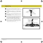
Страница 31: ...Hub bottom of motor Adapter Plate Cubierta inferior Rubber Gasket 4 Cuchillas Empulgueras Lavadoras de fibra Inserte la cuchilla a través de la ranura de la carcasa Alinee los orificios de la paleta y el conjunto del motor del ventilador y asegúrelos con las arandelas de fibra y los tornillos de fijación de las paletas Asegúrese de que los tornillos estén APRETADOS Los tornillos del motor flojos p...

Страница 32: ...gúrese de que la energía esté apagada antes de instalar Instale bombillas LED de 8 x 4 W incluidas Levante la pantalla de vidrio contra el portalámparas y gírela en el sentido de las agujas del reloj hasta que quede ajustada NO APRIETE DEMASIADO Restaurar la energía está lista para funcionar Cortinas de vidrio Bombillas ...

Страница 33: ...transmisor de pared en la caja de salida de pared existente usando los tornillos provistos Fije la placa de pared con los tornillos de montaje para finalizar la instalación Figura 2 Transmisora Placa de pared decorativa 1 2 4 3 2020 Hinkley Lighting Inc hinkley com 13 Conecte el cableado desde el receptáculo del interruptor de pared a la unidad transmisora de pared Conecte un cable NEGRO de la par...

Страница 34: ... velocidad del ventilador de la siguiente manera I velocidad mínima II baja velocidad III velocidad media baja IV velocidad media V velocidad media alta VI alta velocidad botón Este botón apaga el ventilador Proceso de emparejamiento Con el ventilador apagado ff restaure la energía del ventilador Mantenga presionado el botón SET durante unos 5 segundos y suéltelo Si se instala un kit de luz opciona...

Страница 35: ... bien atornilladas en los brazos de las cuchillas Verifique que todos los brazos de la cuchilla estén firmemente sujetos al motor 2 Verifique que el juego de luces si lo hay esté bien sujeto a la caja del interruptor y que todos los artículos de vidrio y cortinas estén bien sujetos La oscilación también puede resultar de las desviaciones más pequeñas en la distancia de la punta de la hoja a la pun...

Страница 36: ... Máximo de 2 ventiladores pueden operar en un circuito a través del control de pared Un máximo de 12 ventiladores pueden operar en un circuito a través de un interruptor de encendido apagado o interruptor cuando se utiliza la aplicación para el control del ventilador sin el control de pared en el circuito GUÍA DE ENERGÍA ESPECIFICACIONES INFORMACIÓN MEDIA DE DESEMPEÑO Y ENERGÍA Flujo de aire CFM E...

Страница 37: ...QUE MEJORAN SU ESPACIO CON COMODIDAD PROPÓSITO Y ESTILO COMO EMPRESA FAMILIAR ESTAMOS COMPROMETIDOS CON EL DISEÑO EL RENDIMIENTO Y LA CALIDAD Y LO QUE ES IMPORTANTE PARA USTED ES PARAMOUNT PARA NOSOTROS PARA UN SURTIDO COMPLETO DE NUESTROS PRODUCTOS Y FUENTES DE LIBROS VISITA HINKLEY COM ...

Страница 38: ...GLOBAL HEADQUARTERS 33000 Pin Oak Parkway Avon Lake Ohio 44012 T 440 653 5500 F 440 653 5555 hinkley com ...

Страница 39: ...MANUEL D UTILISATION DU VENTILATEUR DE PLAFOND 36 SAWYER VENTILATEUR LED INTÉRIEUR EXTÉRIEUR LED WET ...

Страница 40: ... Si vous avez besoin d aide supplémentaire ou avez des questions n hésitez pas à nous contacter Pour des informations sur la garantie visitez hinkley com SERVICE HINKLEY COM 800 HINKLEY LET S SEE THAT HINKLEY STYLE HINKLEY HINKLEYSTYLE NOUS VOULONS VOUS AIMER VOTRE NOUVEAU FAN NOUS SOMMES ICI SI VOUS AVEZ UNE QUESTION BESOIN D UNE AIDE OU VOULEZ CHAT SUR NOS PRODUITS ENVOYER DES SUGGESTIONS NOTRE ...

Страница 41: ...DE SÉCURITÉ IMPORTANTES OUTILS ET MATÉRIAUX REQUIS DÉBALLAGE DE VOTRE FAN PRÉPARATION INSTALLATION DU SUPPORT DE SUSPENSION SUSPENDRE LE VENTILATEUR CONNECTIONS ELECTRIQUES FIN DE L INSTALLATION INSTALLATION DES LAMES 10 10 11 12 13 14 14 15 15 15 INSTALLATION DE LA PLAQUE DE MONTAGE INSTALLATION DES AMPOULES À LED ET DES TEINTES DE VERRE INSTALLATION DE LA COMMANDE MURALE OPÉRATION ENTRETIEN ET N...

Страница 42: ...es doivent être à au moins 7 pieds du sol Les lames doivent être fixées une fois le boîtier du moteur suspendu et en place Le boîtier du moteur du ventilateur doit être conservé dans le carton jusqu à ce qu il soit prêt à être installé pour protéger sa finition Si vous installez plusieurs ventilateurs de plafond assurez vous de ne pas mélanger des ensembles de pales de ventilateur car chaque pale ...

Страница 43: ...port du ventilateur et peuvent devoir être remplacés Consulter un électricien qualifié en cas de doute N utilisez pas de gradateur de lumière incandescente N utilisez pas ce ventilateur avec un dispositif de contrôle de vitesse de ventilateur de type transformateur Pour réduire le risque de blessures corporelles ne pliez pas les bras des pales lors de leur installation de l équilibrage des pales o...

Страница 44: ...vis rondelles de blocage rondelles en étoile rondelles plates écrous de fil vis de la lame au moteur avec rondelles en caoutchouc Joint en caoutchouc Kit d équilibre Quincaillerie de câble de sécurité vis à bois rondelle plate XX FINITION DU VENTILATEUR Récepteur Incl 5 fil écrou Commande murale avec plaque murale de batterie 12v plaque frontale 2 jeux de vis de montage et de vis mécaniques Ampoul...

Страница 45: ...d doit être mis à la terre par mesure de précaution contre un éventuel choc électrique 1 2 3 4 Localisez la solive de plafond à l endroit où le ventilateur doit être installé en vous assurant que l emplacement est conforme aux exigences de la section dégagement minimum de ce guide Les solives de bois doivent être solides et de taille adéquate pour supporter 35 livres voir page 2 éléments 3 et 4 S ...

Страница 46: ...ige de descente au lieu de la goupille d attelage de l accouplement sur le dessus de l assemblage du moteur Fig 2 Faites passer soigneusement les fils électriques et le câble de sécurité du ventilateur à travers la tige de descente Vissez la tige descendante dans le coupleur jusqu à ce que les trous s alignent Insérez la goupille de la tige descendante dans les trous du collier de montage et de la...

Страница 47: ...électriques Faites glisser l auvent vers le haut et fixez le au support de suspension avec 4 vis fournies Fig 3 Fil de terre Tige descendante Broche croisée Câbles de branchement 3 Vis de réglage Couverture de joug Canopée Anneau de garniture Anneau en C Câble de sécurité Fig 4 INSTALLATION DU SUPPORT DE CÂBLE DE SÉCURITÉ Fixez la vis à bois et la rondelle plate à la solive du plafond comme illust...

Страница 48: ...E Connectez le fil de ventilateur GRIS au fil de récepteur GRIS Connectez le fil neutre du ventilateur ROUGE au fil neutre du récepteur ROUGE Connectez le fil neutre du ventilateur BLANC au fil neutre du récepteur BLANC Connectez le fil neutre du ventilateur BLEU au fil neutre du récepteur BLEU 3 Connectez le câblage du plafond à l unité de réception Utilisez le faisceau de 2 fils sur le récepteur...

Страница 49: ...en serrés Desserrez les boucles à une extrémité de la chaîne et attachez les aux boucles de support de chaîne du luminaire Desserrez les boucles restantes des extrémités de la chaîne et installez la chaîne sur l anneau en C sur la tige du ventilateur Faites glisser le C Ring sur la tige descendante jusqu à ce que les chaînes se moquent Fixez l anneau en C en position sur la tige descendante en fix...

Страница 50: ... le joint en caoutchouc et la plaque d adaptation sur les 2 vis précédemment desserrées tournez la plaque d adaptation jusqu à ce qu elle se verrouille en place dans la section étroite des trous de clé Fixez en serrant les 2 vis précédemment desserrées et celle précédemment retirée Soulevez le couvercle inférieur contre la plaque d adaptation avec 2 vis jusqu à ce qu il soit bien serré L alimentat...

Страница 51: ...que l alimentation est coupée avant l installation Installez 8 ampoules LED de 4 W incluses Soulevez l abat jour en verre contre le support de lumière et tournez dans le sens des aiguilles d une montre jusqu à ce qu il soit bien serré NE PAS TROP SERRER L alimentation de restauration est prête à fonctionner Abat jour en verre Blubs ...

Страница 52: ...ctez le fil de terre vert de l interrupteur au fil de terre du boîtier de prise murale Installez l émetteur mural sur la boîte murale existante à l aide des vis fournies Fixez la plaque murale avec les vis de montage pour terminer l installation Fig 2 Connectez le câblage de la prise murale à l émetteur mural Connectez un fil NOIR du mur à un fil NOIR étiqueté TO FAN de l émetteur mural Connectez ...

Страница 53: ...e moyenne V vitesse moyenne élevée VI haute flèche Bouton de marche arrière Ce bouton sert à contrôler la direction du ventilateur Ce bouton doit être enfoncé pendant le fonctionnement du ventilateur vitesse suggérée IV Bouton d éclairage Ce bouton sert à contrôler la lumière en option Mettez l interrupteur DIP D et ON à l avant de l émetteur pour décider de la lumière en ON OFF ou Dimmable Proces...

Страница 54: ...t ajustez la ou les lames de sorte que les distances soient égales 4 L échange de lames adjacentes peut redistribuer la masse et permettre un fonctionnement plus fluide Les bras de lame peuvent être légèrement pliés pour redonner le même pas à toutes les lames si une lame est différente des autres lames lorsque le bord est vu 5 La plupart des oscillations peuvent être attribuées à une boîte électr...

Страница 55: ...re ou Google Play Ouvrez l application pour créer votre compte Vous pouvez également vous connecter avec votre compte Facebook ou Google Ensuite configurez une connexion WiFi Vous aurez besoin du SSID et du mot de passe WiFi pour le réseau auquel vous souhaitez vous connecter Vous serez invité à choisir la finition de votre ventilateur et à nommer votre périphérique de ventilateur L application vo...

Страница 56: ...ÉLIORENT VOTRE ESPACE AVEC CONFORT OBJECTIF ET STYLE EN TANT QU ENTREPRISE FAMILIALE NOUS NOUS ENGAGEONS À CONCEVOIR PERFORMANCE ET QUALITÉ ET CE QUI EST IMPORTANT POUR VOUS EST PARAMOUNT POUR NOUS POUR UN ASSORTIMENT COMPLET DE NOS PRODUITS ET LIVRES DE SOURCE VISITEZ HINKLEY COM ...

Страница 57: ...GLOBAL HEADQUARTERS 33000 Pin Oak Parkway Avon Lake Ohio 44012 T 440 653 5500 F 440 653 5555 hinkley com ...

Отзывы: