Hiniker 9850 Скачать руководство пользователя страница 8

PLOWING SNOW

WARNING: Always wear a seat belt when 
plowing snow. Sudden contact with a hid-
den object can result in serious personal 
injury.

Inspect areas to be plowed before snowfall for poten-
tial hazards, and mark obstructions with stakes that 
will be seen when snow covers the ground. Identify 
any emergency equipment and utility outlets that 
may need to be cleared in the event of a storm. Pre-
pare a plan beforehand for clearing snow from tight 
or enclosed areas and locate sites for stacking snow.

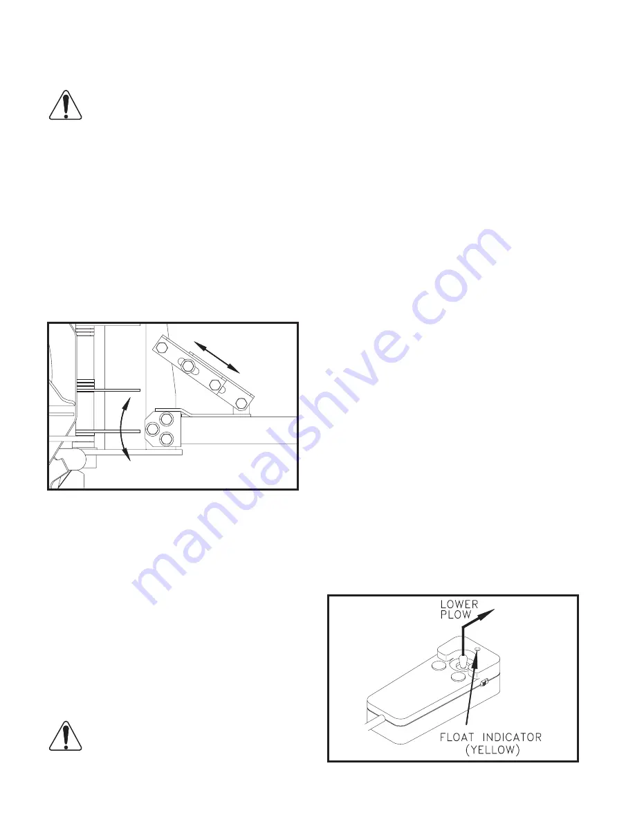
Level the plow in the scoop position by loosening 
the hardware through the front of the pushframe and 
through the diagonal braces to allow the plow to set-
tle to the ground. Retighten the hardware once the 
plow is level.

DWG. NO. 5996

Adjust the skids at the back of the moldboard ac-
cording to the surface to be plowed. The bottom of 
the skids should be about 1/2” below the cutting edge 
when plowing gravel roads or lots. Skids should be 
even with the cutting edge on hard surfaces such as 
asphalt or concrete.

Always plow snow as it is accumulating. Wet snow 
may weigh about 12 pounds per cubic foot. The weight 
of snow being pushed by your plow may increase to 
several tons.

Allowing snow depth to grow to unmanageable lev-

els can cause difficult removal problems and can be 

costly in terms of wear on  equipment.

WARNING: Serious personal injury can re-
sult from plowing at excessive speeds, as 
well as costly damage to equipment and 

property, if an obstruction is encountered while 
plowing. Do not exceed 10 mph while plowing.

Plow snow in the lowest truck gear to transfer maxi-
mum power to the cutting edge. Clear areas in front 

of buildings first. Backdrag snow away from buildings 

by driving to the building with the plow raised, then 
dropping the blade to pull snow away. Push snow to 
outer edges of the lot after snow is away from build-
ings.

Begin clearing large lots by putting the plow in the V-
position and creating a single path. Roll snow to the 
outer edges of the lot by taking successive passes 
with the blade angled, or put the plow in the scoop 
position and push snow to the end of the lot. Break 
up hard snowbanks with the plow in the V-position.

When plowing very deep snow, it may be necessary 
to raise the blade and shear off layers of snow until a 
working area is cleared. Work small areas in multiple 
passes to push snow to outer edges. Generally, 6 
inch snow can be plowed with the entire blade width; 
9 inch snow with 3/4 of the blade width; 12 inch snow 
with 1/2 of the blade width. Local conditions will de-
termine how much work can be done before stalling 
or getting stuck.

PARKING 

Lower the plow to the ground when parking your 
truck for a long period of time with the plow attached. 
Place the on/off switch in the “off’ position to prevent 
the plow from drawing power from the truck battery. 
The plow’s power unit may continue to draw electri-
cal current from the truck battery if the control switch 

is left on; possibly resulting in insufficient charge to 

start the truck.

REMOVING THE PLOW

To remove the snowplow from your truck, park on a 
solid level surface with the blade straight across the 
truck. Lower the plow to the ground and leave the 

controller in the “float’ mode.

Lower Plow, Leave Controller In “Float”   DWG. NO. 4163

6  Operating Procedures

Содержание 9850

Страница 1: ...PICKUP TRUCK SNOWPLOW V PLOW Models 9850 9950 OPERATOR S MANUAL DO NOT USE OR OPERATE THIS EQUIPMENT UNTIL THIS MANUAL HAS BEEN READ AND THOROUGHLY UNDERSTOOD PART NUMBER 25012268 Rev C ...

Страница 2: ......

Страница 3: ...FETY 3 OPERATING PROCEDURES 4 TROUBLE SHOOTING 9 MAINTENANCE 11 ASSEMBLY 13 SYSTEM CHECK OUT AND JOYSTICK CONFIGURATION 24 HEADLAMP AIMING PROCEDURE 25 SPECIFICATIONS 30 WARRANTY 31 Table of Contents 1 25012268RevC 3 10 Hiniker 25012268RevC ...

Страница 4: ... serious injury can result All references to Left or Right are defined as viewing the plow from the cab of the truck Instructions for raising and lowering the plow refer to the joystick controller as received from the factory The raise and lower functions may be reversed to suit the preference of the opera tor by following the instructions on page 24 for switching the controller joystick and face ...

Страница 5: ...tempt to handle or service this equipment or direct others to do the same unless you know how to do it safely and have the proper tools for the job 5 Keep hands feet hair and clothing away from moving parts 6 Do not alter the equipment to the extent of compromising safety or performance SAFETY BEFORE OPERATION 1 Discipline yourself to visually check for worn damaged or cracked parts before startin...

Страница 6: ...einstall the pin in the plate for transport Pull the latch handle into the clevis on the lift frame to force the sliders through the notches in the prongs and receivers Check that both sliders are fully engaged Pin the handle in the clevis with its klik pin Failure to pin the handle in place may allow the plow to fall off the truck Handle Pinned With Plow On Truck DWG NO 6003 Plug in the three ele...

Страница 7: ... plow reaches the de sired height Moving the joystick to the Lower po sition will lower the blade to the ground and allow the plow to Float along the contour of the ground while plowing snow The green light on the control box will turn yellow to indicate the plow is in the float mode Momentarily moving the joystick to the Raise position will remove the plow from the float mode and the yellow light...

Страница 8: ...snow in the lowest truck gear to transfer maxi mum power to the cutting edge Clear areas in front of buildings first Backdrag snow away from buildings by driving to the building with the plow raised then dropping the blade to pull snow away Push snow to outer edges of the lot after snow is away from build ings Begin clearing large lots by putting the plow in the V position and creating a single pa...

Страница 9: ...ks to full retract the lift cylinder rod Retract Cylinder With Upper Lift Links DWG NO 6000 Rotate the stop plate up to contact the spacer bushing on the lift cylinder bolt Rotate Stop Plate DWG NO 6004 Gently push back on the headlight bracket to tilt the frame back as far as possible then release the bracket to allow the weight of the lift frame to lock the stop plate in place Operating Procedur...

Страница 10: ...d lights to the truck and switch power off on the snowplow control box then slowly back the truck out from the plow Turn Off Lights And Power DWG NO 4164 NOTE The stop plate will automatically fall for ward as soon as the lift cylinder is fully extended for raising the blade prior to transporting the plow If the snowplow won t be used for an extended pe riod of time the prong weldment can be remov...

Страница 11: ...il A Charge or replace battery B Add oil do not overfill C Tighten or redo connection D Replace valve A Clean valve or replace B Clean valve or replace C Repack or replace cylinder D Replace control box POSSIBLE CAUSE A Receivers are tipped for ward B Prongs recoil out of receiv ers when attaching C Park stand pinned too low A Defective solenoid B Defective pump motor C Weak or defective battery D...

Страница 12: ... warms the oil will thin out and function normally B Select Hiniker Cold Flow Hydraulic Oil for plowing in extremely cold tempera tures A Add hydraulic oil until chat tering stops Do not over fill A Avoid excessive inclines or change direction of plow ing B Remove excess oil A Add coolant B Remove ice and snow C Transport plow at lower speeds A Move switch to plow posi tion B Replace relay C Repla...

Страница 13: ...r for best performance Select Hiniker Cold Flow Hy draulic Oil or an equivalent oil that meets mili tary specification 5606 for plowing in extremely cold temperatures Change hydraulic oil with the wings in the V position and the plow on the ground Discon nect three electrical wiring harnesses from the power unit and uncouple five hydraulic lines Unbolt the power unit from the plow and re move it t...

Страница 14: ...ng or mast sections to avoid damage to these components The 5 16 hex bolts in the latch sliders are fac tory retained with anaerobic threadlock If re moval or replacement of these bolts is neces sary purchase new bolts with threadlocker from your Hiniker dealer or apply a commercially available threadlock i e Loctite 242 blue to standard 5 16 18 x 3 4 grade 5 hex bolts be fore reassembly ELECTRICA...

Страница 15: ... grade 5 bolts and equivalent type B and type F lock nuts Type B lock nuts are plain hex type F lock nuts are flanged hex PLOW ASSEMBLY 1 Lift the snowplow moldboard assembly to a clear level working area by hooking hoist chains through the two holes in the top plate of the center mast The hoist should be capable of lifting at least 1 000 lb loads Remove two side markers and 5 16 inch hard ware fr...

Страница 16: ...on DWG NO 6001A Move the frame assembly to the back of the moldboard assembly and align three sets of holes at the front of the frame assembly with holes through the moldboard center mast Place a flat washer onto the three hex bolts before inserting them through the holes Secure the bolts with flat washers and lock nuts Pin the parking stand to hold the square tubes of the pushframe parallel to th...

Страница 17: ...e lift frame scrape a small amount of paint from the two mount holes in the lift frame to pro vide a good electrical ground for the turn signals and parking lights Mount the power unit on the lift frame with two 3 8 inch x 3 4 inch hex bolts and two 3 8 inch lock washers The plastic reservoir of the power unit should be to the left side of the of the plow see following illustration DWG NO 6454A Lo...

Страница 18: ...nd measures about 38 inches long The wiring harness has a ten pin connector and a three pin connector on one end and the other end has connectors labeled DRIVER SIDE and PSNGR SIDE for the headlamps and six loose wires with spade receptacles and one wire with a ring terminal The ground wire harness has a ring terminal and six spade receptacles on two wires DWG NO 6456A Connect port C on the power ...

Страница 19: ...ness as shown DWG NO 5844B Connect the Tan wire of the wiring harness to the spade terminal on solenoid S1 Connect the Pink wire to solenoid S2 Connect the Gray wire to solenoid S3 Connect the Brown wire to solenoid S4 Connect the Blue with White stripe wire to solenoid S5 Connect the Blue wire to solenoid S6 Connect the RH headlamp to the har ness end labeled PSNGR SIDE and the LH headlamp to the...

Страница 20: ...e harness in it s approximate position for final assembly with the 7 pin and 3 pin circular connectors near the drivers side firewall the 10 pin and 3 pin connectors just left of center near the grill the relays near the drivers side in ner fender and the 5 pin headlight connec tors at the respective headlights 9 Determine the location of the vehicle bat tery If the battery is located on the right...

Страница 21: ... and install the 4 inch grommet in the hole if re quired CAUTION Ensure that the relays will clear any hood lift spring mechanisms before installation 11 Select an area near the drivers side fend er for the relays Drill three 1 8 diameter holes and secure the relays with 8 x 1 2 inch self tapping screws from the hardware bag in the parts box 12 Splice the red with white stripe wire to the vehicle ...

Страница 22: ...ck wires from the harness to the minus post of the ve hicle s battery Connect the Red or Red striped cable to the motor solenoid Route the power cable to the grill near the 10 pin connector DWG NO 6473 Connect the Red fused wire from the har ness and the 24 inch Red cable to the plus terminal of the battery or battery access post Connect the other end of the 24 inch Red cable to the motor solenoid...

Страница 23: ...l wire Using a blue splice crimp the single green wire from the underhood harness into the vehicle s curbside turn signal wire 19 Select the proper headlight adapter for your vehicle specific instructions are included with each kit The headlight adapter kit consists of two identical adapters Install the adapters ac cording to the instructions included with the kit and connect to the 5 pin connecto...

Страница 24: ...hrough the notches in the prongs and receivers Pin the handle in the clevis with its klik pin DWG NO 5995 22 V Plow Assembly Raise the parking stand to its highest posi tion and repin Connect the three electrical cables from the plow to their corresponding receptacles on the truck DWG NO 5232 21 Select Hiniker Cold Flow Hydraulic Oil or an equivalent oil that meets military speci fication 5606 for...

Страница 25: ... hardware through the front of the pushframe and through the diagonal braces to allow the plow to settle to the ground Re tighten the hardware once the plow is level 23 Fasten the power unit cover assembly to the lift frame bracket with two 1 4 inch x 3 4 inch screws flat washers and lock nuts from the hardware bag in the parts box Tighten the lock nuts so that the assembly is secure yet the cover...

Страница 26: ...e joystick is pushed forward These functions can be reversed by reassembling the joystick switch and face plate To reverse the face plate pry the plate away from the controller by inserting a small screwdriver along the side of the plate at location 1 in drawing 5855 Flip the plate over then reinstall by gently squeezing the long sides together and sliding the four tabs into slots in the controlle...

Страница 27: ...s lines 3 and 4 offset 20 1 2 inches 52 cm from the first line representing the distance between the two plow headlamps 3 Measure the height from the ground to the center of the plow headlamps then mark a horizontal line line 2 on the wall at that same height 4 Refer to the following chart then mark a sec ond horizontal line below the first line 5 as required Headlamp Centerline Height Vertical Ai...

Страница 28: ...26 Wiring Harness ...

Страница 29: ...Wiring Harness 27 DWG NO 5857 ...

Страница 30: ...28 V Plow Power Unit DWG NO 6457A ...

Страница 31: ...Power Unit Hydraulic Circuit Diagram 29 DWG NO 6459 ...

Страница 32: ... 8 X 6 1084 Steel WEIGHT w o SNOW DEFLECTOR Does Not Include Weight Of Mount Kit 783 lb 817 lb RECOMMENDED HYDRAULIC FLUID Hiniker Cold Flow Mil Spec 5606 Or Equivalent HYDRAULIC FLUID CAPACITY 3 QTS HIGH BEAM HEADLIGHT BULB One H1 12V 55W LOW BEAM HEADLIGHT BULB One H7 12V 55W TURN SIGNAL PARKING BULB One 1157 Heavy Duty Double Contact 32 3 C P MOTOR SOLENOID 12 VDC solenoid continuous duty seale...

Страница 33: ...pacity substitution of parts not approved by Hiniker Company or any alteration or repair in such manner as in our judgment affects the product materially and adversely shall void this warranty Hiniker reserves the right to make improvements or changes to any of it s products without notice Such improvements or changes shall not trigger any obligation by Hiniker to update modify or change any produ...

Отзывы: