English
11
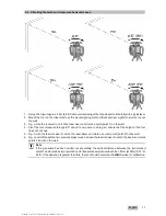
5.6 Checking the main and transverse horizontal axes
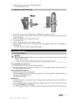
1. Set up the tripod approx. 20 m (66 ft) from a wall and adjust the tripod head horizontally with a spirit level.
2. Mount the tool on the tripod and use the visual sighting method (front and rear sights) to aim the tool at
the wall.
3. Fig. a: Use the receiver to catch the laser beam and mark a point (point 1) on the wall.
4. Pivot the tool clockwise through 90° about its own axis. In doing so, ensure that the height of the tool
does not change.
5. Fig. b: Use the laser receiver to catch the laser beam and mark a second point (point 2) on the wall.
6. Fig. c and d: Repeat the two previous steps twice and use the laser receiver to catch the beam and mark
points 3 and 4 on the wall.
Note
If the procedure has been carried out accurately, the vertical distance between the two marked
points 1 and 3 (main axis) or points 2 and 4 (transverse axis) should each be < 2 mm (at 20 m) (0.12" at
66 ft). If the deviation is greater than this, the tool should be returned to
Hilti
Service for calibration.
Printed: 31.07.2017 | Doc-Nr: PUB / 5260662 / 000 / 01
Содержание PR 2-HS A12
Страница 1: ...PR 2 HS A12 English Printed 31 07 2017 Doc Nr PUB 5260662 000 01 ...
Страница 2: ...Printed 31 07 2017 Doc Nr PUB 5260662 000 01 ...
Страница 19: ...Printed 31 07 2017 Doc Nr PUB 5260662 000 01 ...
Страница 20: ...Hilti registered trademark of Hilti Corp Schaan 20170720 Printed 31 07 2017 Doc Nr PUB 5260662 000 01 ...


