background image

10

English

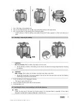
1. Mount the laser on a suitable holder or bracket.

2. Press the ' button.

The auto-leveling LED blinks green.

The laser switches on, the beam begins to rotate and the “auto leveling” LED lights as soon as the

tool has leveled itself.

Note

A wall bracket or tripod may be used as mounting devices. The angle of inclination of the surface

on which it stands should not exceed ± 5°.

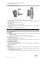
5.4 Using the slope adapter to set the slope

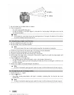
1. Mount a suitable slope adapter on a tripod.

2. Mount the laser tool on the slope adapter.

Note

The control panel of the laser tool should face away from the direction of inclination.

3. Position the tripod either at the upper edge or lower edge of the inclined plane.

4. Make sure that the slope adapter is in the zero position (0°).

5. Position yourself behind the laser tool, facing the control panel.

6. With the aid of the target notch on the head of the laser tool, adjust the tool with the slope adapter until

it is parallel to the inclined plane.

7. Press the

button on the laser tool.

The inclined plane mode LED then lights on the control panel of the laser tool.

The laser tool then begins automatic self-leveling. The laser switches on and begins to rotate as soon

as this is complete.

8. Set the slope adapter to the desired angle of inclination.

Note

To return to standard operating mode, switch the laser tool off and then switch it back on again.

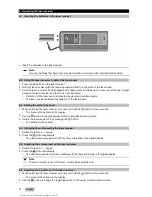
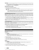
5.5 Deactivating the shock warning function

1. Switch the laser on. → page 9

2. Press the

button.

The shock warning deactivation LED lights constantly, indicating that the function has been

deactivated.

Note

To return to standard operating mode, switch the laser tool off and then switch it back on again.

Printed: 31.07.2017 | Doc-Nr: PUB / 5260662 / 000 / 01

Содержание PR 2-HS A12

Страница 1: ...PR 2 HS A12 English Printed 31 07 2017 Doc Nr PUB 5260662 000 01 ...

Страница 2: ...Printed 31 07 2017 Doc Nr PUB 5260662 000 01 ...

Страница 3: ...ps in the text Item reference numbers are used in the overview illustration In the product overview section the numbers shown in the legend relate to these item reference numbers 1 2 On the product Laser information Laser Class 2 based on the IEC60825 1 EN60825 1 2007 standard in com pliance with CFR 21 1040 Laser Notice 50 Do not stare into beam 1 3 About this documentation Read these operating i...

Страница 4: ...y Hilti may restrict the user s authorization to operate the equipment You must check the accuracy of the tool after it has been dropped or subjected to other mechanical stresses When the tool is brought into a warm environment from very cold conditions or vice versa allow it to become acclimatized before use Make sure that the tool is mounted securely when adapters or accessories are used Keep th...

Страница 5: ...e There is a risk of explosion Do not disassemble squash or incinerate batteries and do not subject them to temperatures over 80 C 176 F This presents a risk of fire explosion or injury through contact with caustic substances Do not subject the battery to hard mechanical impacts and do not throw the battery Batteries must be kept out of reach of children Avoid ingress of moisture Ingress of moistu...

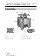
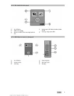
Страница 6: ...location well away from flammable materials where it can be kept under observation and allowed to cool down 3 Description 3 1 Overview of the product 3 1 1 PR 2 HS A12 rotating laser Laser beam plane of rotation Rotary head Grip Battery release button Li ion battery Battery charge status display Control panel Base plate with 5 8 thread Printed 31 07 2017 Doc Nr PUB 5260662 000 01 ...

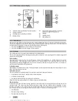
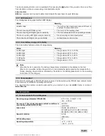
Страница 7: ...g Button and LED Shock warning deactiva tion Button and LED Manual inclined plane mode Battery charge state LEDs 3 1 3 PRA 20 laser receiver control panel On off button Volume button Units key Receiving area Marking notch Display Printed 31 07 2017 Doc Nr PUB 5260662 000 01 ...

Страница 8: ... Auto leveling is active within the 5 range relative to the horizontal plane and can be deactivated by pressing the button The tool can be set up directly on the ground or floor on a tripod or with the aid of suitable mounting brackets Inclination angle Alternatively in inclined plane mode the slope adapter can be adjusted manually to achieve slopes of up to 60 Auto leveling is not active Automati...

Страница 9: ...s light Charge status 25 to 50 1 LED lights Charge status 10 to 25 1 LED blinks Charge status 10 Note When the tool is in operation the battery charge status is indicated in the display on the tool When not in operation battery charge state can be indicated by lightly pressing the release button During charging charge state is indicated by the LEDs on the battery please refer to the operating inst...

Страница 10: ...me without detection before automatic power off 15 min Drop test height in the PRA 83 laser receiver holder under standard ambient conditions in accordance with MIL STD 810G 6 ft 10 in 2 m Operating temperature 4 122 20 50 Storage temperature 13 140 25 60 Weight including batteries 0 55 lb 0 25 kg Protection class in accordance with IEC 60529 IP66 5 Operating the rotating laser 5 1 Handling the la...

Страница 11: ...efore inserting the battery CAUTION Risk of injury If the battery is not fitted correctly it may drop out and fall Check that the battery is securely seated in the tool so that it cannot drop out and fall thereby presenting a hazard to other persons 1 Push the battery in until it engages securely The laser is ready to switch on 2 Press the release button and hold it in this position 3 Pull the bat...

Страница 12: ...osition yourself behind the laser tool facing the control panel 6 With the aid of the target notch on the head of the laser tool adjust the tool with the slope adapter until it is parallel to the inclined plane 7 Press the button on the laser tool The inclined plane mode LED then lights on the control panel of the laser tool The laser tool then begins automatic self leveling The laser switches on ...

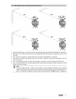
Страница 13: ...n doing so ensure that the height of the tool does not change 5 Fig b Use the laser receiver to catch the laser beam and mark a second point point 2 on the wall 6 Fig c and d Repeat the two previous steps twice and use the laser receiver to catch the beam and mark points 3 and 4 on the wall Note If the procedure has been carried out accurately the vertical distance between the two marked points 1 ...

Страница 14: ... on press and hold the button for two seconds The menu is then shown in the display 2 Use the button to toggle between metric or imperial measuring units 3 Switch the laser receiver off by pressing the button The settings will be saved 6 4 Changing the units used by the laser receiver 1 Switch the laser on page 9 2 Press the button repeatedly The desired accuracy mm cm off is shown alternately in ...

Страница 15: ...o severe injury and burns Always remove the battery before carrying out care and maintenance tasks Care and maintenance of the tool Carefully remove any dirt that may be adhering to the tool Use only a slightly damp cloth to clean the casing Do not use cleaning agents containing silicone as these may attack the plastic parts Care of the lithium ion batteries Keep the battery free from oil and grea...

Страница 16: ...of his her obligation to check the product before and during use 7 3 Checking accuracy In order to ensure compliance with the technical specifications the tool should be checked regularly at least before each major relevant measuring task After falling from considerable height the tool should be checked for correct accurate operation When the following conditions are fulfilled it can be assumed th...

Страница 17: ... present a health hazard Batteries may explode if damaged or exposed to very high temperatures causing poisoning burns acid burns or environmental pollution Careless disposal may permit unauthorized and improper use of the equipment This may result in serious personal injury injury to third parties and pollution of the environment Dispose of defective batteries right away Keep them out of reach of...

Страница 18: ...16 English Note Changes or modifications not expressly approved by Hilti may restrict the user s authorization to operate the equipment Printed 31 07 2017 Doc Nr PUB 5260662 000 01 ...

Страница 19: ...Printed 31 07 2017 Doc Nr PUB 5260662 000 01 ...

Страница 20: ...Hilti registered trademark of Hilti Corp Schaan 20170720 Printed 31 07 2017 Doc Nr PUB 5260662 000 01 ...

Отзывы: