


3.2.2 Installation Technique - RS485 / RS422
Under certain conditions, the RS485 as well as the RS422 interfaces are very free
from interference and are suitable for longer distances. Both interface types per-
mit the networking of several communication participants. The data transfer oc-
curs as a differential signal between the data line Data/Data
¯¯¯¯. In contrast to the
RS485 interface, the RS422 interface utilizes separate data lines for sending and
receiving directions, thus a total of four conductors (TxData/TxData
¯¯¯¯¯¯ and RxDa-
ta/RxData
¯¯¯¯¯¯). The differential signal is always transferred over twisted wire pairs.
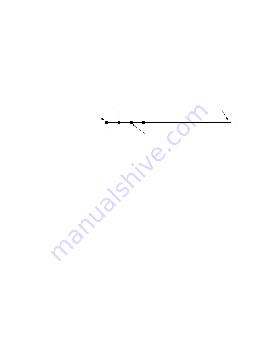
A Bus structure with RS485/RS422 has the following form:
Typical Form of a RS485/RS422 Bus structure
The
main line
determines the length of the communication path. It is terminated
at both ends with the terminators and preferably at the end with the level
resistance.
The
Spur line
s should not exceed a length of 2.5m. They are branched off via
Bus branches
from the main line. In practice, so-called Bus clamps (e.g. from
Siemens) or T-pieces (e.g. from the Weidmüller company) are used as branches.
There are several possibilities regarding the wiring of the reference potential.
These have a plug for the input and output of the main line and a plug for the spur
line. As a rule in the branches, the level and/or the end resistors can be switched
on or off via Dip switches.
Wiring by means of screw clamps should be avoided as these usually lead to
transfer interferences with high Baud rates.
When using finished Bus branches, special account must be taken with the shiel-
ding concept and the pin assignment of the clamps!
Main line
Spur line (<2.5m)
Communication device
Branch / Bus clamp
2-wire RS485
4-wire RS422
End of the
main line
End of the
main line
Appendix
18
Copyright * Hilscher Gesellschaft für Systemautomation mbH * Hotline/Support: +49(0)6190/9907-99 * De:P30COS#3E


