background image


25 


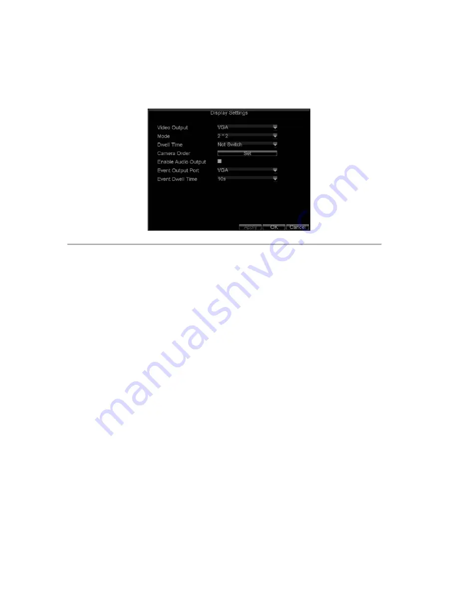
Configure Live Preview Display 


Click Menu >Settings >Display to access the Live Preview display settings:   


Figure 4. Display Settings 


Configure the following settings for Live Preview Display:   


Video Output: 

Set the video output modes, including VGA, Aux Output and Main CVBS.   


Mode: 

Set the live view display mode to be 1×1, 2×2, 3×3, or 4×4. 


Dwell Time:

 Set the dwell time for camera switching when 

Start Auto-switch 

is selected in Live 

Preview.   


Camera Order:

 Set the camera order for display in the selected mode (See 

Setting Camera Order

). 


Enable Audio Output: 

Enable/disable audio output for the selected video output.   


Event Output Port: 

Set the port for event output to be VGA, Main Vout or Auxiliary Vout.   


Event Dwell Time:

 Set the dwell time for event video display.  


Note:


1.


   W

ill automatically detect whether this is VGA display connected or not.   

2.


When a VGA display  is connected to DVR, then the VGA will  be used  as the main video output, and all  menu 
operations are accessible  by mouse, front panel or IR remote;  the VIDEO OUT1  will be  used as the spot video 
output which only allows user to access the live view of the camera according to the configured CVBS video 
parameters; and the VIDEO OUT2 will be used as the auxiliary video  output,  which allows user to  access the 
single-camera live view of the camera as well as press the 

3DEF/F2

 button on the front panel to switch the camera 

display. 

3.


When there is no VGA display connected to DVR, the VIDEO OUT1 will be used as the main video output, and 
menu operations are accessible; the VGA will be used as the spot video output which only allows user to access 
the live view of the camera according to the configured VGA video parameters; and the VIDEO OUT2 is used as 
the auxiliary video output which allows user to access the single-camera live view of the camera as well as press 
the 

3DEF/F2

 button on the front panel to switch the camera display.   

4.


The connection or disconnection of VGA display in the process of device running will not affect its functions as 
shown above.   


Set Camera Order 


The Camera Order settings allow you to set camera sequence in selectable live view display mode. See the following 
figure: 


Содержание VC-SYS-16H301A Series

Страница 1: ...VC SYS 4H101A 8H201A 16H301A Series DVR USER MANUAL Version 1 0 2...

Страница 2: ...a rack or shelf Major shocks or jolts to the unit as a result of dropping it may cause damage to the sensitive electronics within the unit Use the DVR in conjunction with an UPS if possible Power dow...

Страница 3: ...eview Display 25 Set Camera Order 25 C H A P T E R 4 27 Record Settings 27 Configure Record Settings 28 Before Record Settings 28 Initializing Record Settings 28 Scheduling a Recording 29 Starting a M...

Страница 4: ...trols 67 Customize Patterns 69 C H A P T E R 1 0 70 Camera Management 70 OSD Settings 71 Display Settings 71 Privacy Mask Settings 72 C H A P T E R 1 1 74 HDD Management 74 Manage HDDs 75 Initializing...

Страница 5: ...4 C H A P T E R 1 Introduction...

Страница 6: ...definition OggVorbis audio compression standard Independent video encoding parameters including frame rate resolution bit rate video quality etc Scheduled and event recording parameters configurable f...

Страница 7: ...in playback Management and maintenance for backup devices Alarm Exception Configurable arming time for alarm in out Various alarm types supported alarms for video loss motion detection video tempering...

Страница 8: ...are source code of Demo Support and training service for application system development Product Application Diagram Figure 4 Product Application Diagram Operating Your DVR There are numerous ways to n...

Страница 9: ...T Switch of compound keys between the numeric letter input and functional control 5 Control Buttons Directional buttons In menu mode the direction buttons are used to navigate between different fields...

Страница 10: ...ect checkbox fields and ON OFF switch In playback mode it can be used to play or pause the video In single frame play mode pressing the Enter button will advance the video by a single frame And in aut...

Страница 11: ...r numeral 7 2 Enter letters PQRS 3 Manual record for direct access to manual record interface manually enable disable record 8TUV PTZ 1 Enter numeral 8 2 Enter letters TUV 3 Access PTZ control interfa...

Страница 12: ...nel 12 DIRECTION ENTER Buttons Same as DIRECTION ENTER buttons on front panel 13 PTZ Same as 8TUV PTZ button on front panel 14 ESC Same as ESC button on front panel 15 RESERVED Reserved 16 F1 Same as...

Страница 13: ...ns on the mouse corresponds to 1 Left Button Single Click Select a component of a menu such as a button or an input field This is similar to pressing the ENTER button on the remote front panel control...

Страница 14: ...ors for analog video input 2 VIDEO OUT VIDEO OUT1 is main video out and VIDEO OUT2 is spot video out 3 AUDIO IN RCA connectors for analog audio input 4 LINE IN RCA connector for audio input 5 AUDIO OU...

Страница 15: ...USB Connector for USB devices 10 POWER Switch for turn on off the device 11 ALARM IN Connector for alarm input ALARM OUT Connector for alarm output RS 485 Interface Connector for RS 485 devices T T pi...

Страница 16: ...SB Connector for USB devices 10 RS 485 Interface Connector for RS 485 devices T T pin connects to PTZ 11 ALARM IN Connector for alarm input ALARM OUT Connector for alarm output 12 12V 12VDC power supp...

Страница 17: ...16 C H A P T E R 2 Getting Started...

Страница 18: ...own Figure 1 Shutdown Menu 2 Select the ShutDown button 3 Click the Yes button Rebooting and Locking Your DVR While in the Shutdown menu Figure 1 you may also reboot or lock your DVR Locking your DVR...

Страница 19: ...Wizard window This will take you to the User Permission window shown in Figure 3 Figure 3 User Permission 2 Navigate to the Admin Password text box 3 Type the admin password into the Admin Password t...

Страница 20: ...ializing the HDD will format and remove all data from it 8 After the HDD has been initialized click the OK button which will take you back to the Setup Wizard window 9 Click Next button to enter the R...

Страница 21: ...e recording schedule and make it record continuously all day Figure 7 Edit Schedule Settings 14 Click the OK button This will take you back to the Schedule tab To copy the schedule to a different chan...

Страница 22: ...Wizard enter the Live View window Setting Date Time It is extremely important to setup the system date and time to accurately timestamp recordings and events To setup date and time 1 Open the Menu wi...

Страница 23: ...22 C H A P T E R 3 Live Preview...

Страница 24: ...ed from motion or alarm Event Alarm Record Figure 1 Live Preview Icons Note Status for video loss alarm is only valid with analog cameras Live Preview Operation In Live View mode you can operate the f...

Страница 25: ...nter Playback mode of the selected camera PTZ Enter PTZ Control mode of the selected camera Digital Zoom Enter Digital Zoom interface of the selected camera Menu Enter Main menu Start Auto switch Enab...

Страница 26: ...nt panel or IR remote the VIDEO OUT1 will be used as the spot video output which only allows user to access the live view of the camera according to the configured CVBS video parameters and the VIDEO...

Страница 27: ...o output port and the display mode 1 1 2 2 3 3 and 4 4 modes selectable 3 Use the direction buttons on front panel to move to the display pane for setting press the Enter button to confirm the selecti...

Страница 28: ...27 C H A P T E R 4 Record Settings...

Страница 29: ...d Settings 1 Click Menu Settings Record to access the Record Settings dialog box shown in Figure 1 Figure 1 General Record Settings 2 Select the camera you want to configure 3 Configure the following...

Страница 30: ...the available HDD space Record Audio Enable or disable audio record of the selected camera Click OK to finish settings and return to the previous menu 5 Press the 3DEF F2 button on DVR front panel to...

Страница 31: ...Select recording Type Recording type can be selected to scheduled or triggered by motion detection and or alarm For more specific settings about motion detection and alarm recordings please refer to t...

Страница 32: ...ked or set the HDD that the files reside on to be read only Lock Unlock Recorded Files To lock or unlock a recorded file 1 Click Menu Video Search to enter the Video Search dialog box shown in Figure...

Страница 33: ...locked files opened lock 6 Click Cancel to exit the Video Search menu Figure 7 Video Search Result List Set HDD to Read Only To set a HDD to read only 1 Click Menu HDD to access the HDD Management dia...

Страница 34: ...click OK to finish the setting Note 1 Once set to read only the HDD cannot be written to until it is set back to read write R W 2 VC SYS 4H101A model can be installed with one HDD only therefore when...

Страница 35: ...34 C H A P T E R 5 Playback...

Страница 36: ...16 11 2009 Mon 11 55 19 Playback Panel Playback Control Panel Figure 1 Playback Interface The Playback Control Panel as shown in Figure 2 provides various control buttons for video playback Audio On O...

Страница 37: ...panel to start playback of all the files found or click the Search button to access the list of search results After search results are presented select the file you want to play back and press Play...

Страница 38: ...hannel Note the record video for playback is of the previous 5 minutes Multi camera Playback 1 Select the cameras from the camera list you want to have simultaneous playback 2 Click to stop the ongoin...

Страница 39: ...face By Using a Mouse 1 Click the Slow Forward button on the Playback Control Panel until the speed changes to Single frame 2 Click the Pause button to advance the video frame by frame By Using the Fr...

Страница 40: ...39 Figure 7 Digital Zoom in Playback Mode...

Страница 41: ...40 C H A P T E R 6 Backup...

Страница 42: ...enu Video Export to enter the Export Video menu shown in Figure1 Figure 1 Export Video 2 Select desired parameters to search for files to export 3 On the toolbar press the Export button to enter the R...

Страница 43: ...s exported from drop down list USB Flash Drive USB HDD DVD Writer If backup device is not recognized Click the Refresh button Reconnect device Check for compatibility from vendor 7 Click Start to begi...

Страница 44: ...playback 3 Repeat for additional clips 4 Click the Quit Playback button to exit from the Playback interface You ll then be prompted to save the clips as shown in Figure 6 Figure 6 Video Clips Saving...

Страница 45: ...the Export menu shown in Figure 7 The Export menu can be accessed by following the steps shown in the previous section See Exporting Files Figure 7 Export Menu Once in the Export menu you may Create N...

Страница 46: ...45 C H A P T E R 7 Alarm Settings...

Страница 47: ...e 2 Select the Advanced tab to enter the Advanced Camera Settings menu shown in Figure2 Figure 2 Advanced Camera Settings 3 Select Motion Detection first and click the Area Settings button to enter th...

Страница 48: ...he Motion Detection Sensitivity shown in Figure 4 Higher sensitivity value corresponds to higher sensitivity level Figure 4 Motion Sensitivity Settings 6 Click OK to return to the motion detection are...

Страница 49: ...to take effect Figure6 Schedule Settings 11 Select the Handle tab to configure exceptions handling Exception trigger options will be described in the next section See Understanding Exception Trigger O...

Страница 50: ...gement Settings 3 Set the alarm input type to be Normally Opened N O or Normally Closed N C 4 Check the checkbox next to Setting and click the Handle button to enter the Alarm Input Handle menu 5 Sele...

Страница 51: ...ule to start recording when an alarm is triggered See Scheduling a Recording Alarm outputs may also be configured in the Alarm Management menu To set up Alarm Output 1 Select the Alarm Output tab This...

Страница 52: ...ing You may also trigger alarm outputs manually through the Manual Alarm menu To trigger alarm outputs manually 1 Click Menu Manual Alarm to enter the Manual Alarm menu Figure 13 Figure 13 Manual Alar...

Страница 53: ...video loss detection 4 Check the Video Loss Detection checkbox to enable this feature as shown in Figure 15 Figure 15 Camera Settings Menu 5 Click the Handle button to enter the Exception Handle menu...

Страница 54: ...gger Options Figure 17 Exception Handle Menu 8 Click OK to finish the settings 9 Repeat above steps to configure settings for other channels Video Tampering Detection The video tampering i e moving ca...

Страница 55: ...a Settings Menu 5 Click the Handle button to enter the Exception Handle menu shown in Figure19 6 Select the Schedule tab Set the schedule you want video loss detection to be enabled Schedule can be se...

Страница 56: ...re full HDD Error Errors occurred during writing of the HDD no HDD installed or HDD had failed to initialize Network Disconnected Disconnected network cable IP Conflict Conflict in IP address setting...

Страница 57: ...Alarm Image handle method For alarms that are triggered simultaneously images will be displayed one at a time every 10 seconds default dwell time A different dwell time can be set by going to Menu Set...

Страница 58: ...57 C H A P T E R 8 Network Settings...

Страница 59: ...lect the General tab Configure the settings on the interface 3 If you have a DHCP server running and would like your DVR to automatically obtain an IP address and other network settings from that serv...

Страница 60: ...PPPOE Settings Your DVR also allows for Point to Point Protocol over Ethernet PPPOE access To set up PPPOE access 1 Click Menu Settings Network to enter the Network Settings menu 2 Select the General...

Страница 61: ...w asked to restart your DVR for settings to take place To check on the status of your PPPoE connection go to Menu Setting Network and select the Network Status tab Configuring DDNS If your DVR is setu...

Страница 62: ...er the User Name and Password registered in the DynDNS network Figure 7 DynDNS Settings NTP Server Settings A Network Time Protocol NTP Server may also be set up on your DVR to maintain accurate curre...

Страница 63: ...Video Surveillance software installed To set up a remote alarm host 1 Enter Network settings menu by clicking Menu Setting Network 2 Select the Advanced tab 3 Click the Set butt next to Host Others to...

Страница 64: ...efault settings you can do so in the Network Settings menu The default server port is 8000 while the default HTTP port is 80 To change the default ports 1 Click Menu Settings Network to enter the Netw...

Страница 65: ...64 C H A P T E R 9 PTZ Control...

Страница 66: ...reset Call a PTZ preset Call Patrol Call a PTZ sequence Call Pattern Call a PTZ pattern Preset Settings Enter PTZ preset configuration menu Patrol Settings Enter PTZ sequence configuration menu Patter...

Страница 67: ...e consistent with the PTZ camera connected Setting PTZ Presets Patrols Patterns The DVR allows you to program presets patrols and patterns for a connected PTZ camera Understanding PTZ Controls The PTZ...

Страница 68: ...Use the PTZ control panel to adjust the position of the preset Select a Preset number and click the Set button to save preset location Clear Preset Select a Preset number and click the Clear button to...

Страница 69: ...ch the PTZ will follow while cycling through the patrol The Duration refers to the time span to stay at the corresponding key point The Speed defines the rate at which the PTZ will move to the current...

Страница 70: ...on the front panel 2 Select the Pattern button to enter the Pattern Management menu shown in Figure 8 Figure 8 Pattern Management Menu 3 Select a Pattern Number 4 To record a new pattern select the R...

Страница 71: ...70 C H A P T E R 1 0 Camera Management...

Страница 72: ...play position including the camera name position and the date time display position Display Settings Display settings such as the brightness contrast saturation and hue can also be adjusted in the Cam...

Страница 73: ...ings Camera to enter the Camera Settings menu 2 Click the Advanced tab to enter the Advanced Camera Settings menu as shown in Figure1 Select channel for privacy mask settings in Camera Figure 1 Advanc...

Страница 74: ...73 Figure2 Setting Mask Area 6 Select Exit to save settings and exit the Mask Area Settings interface...

Страница 75: ...74 C H A P T E R 1 1 HDD Management...

Страница 76: ...alized 3 Click the Init button 4 Select OK button to start initialization After the HDD has been initialized the status of the HDD will change from Abnormal to Normal Set HDD Groups Your DVR can separ...

Страница 77: ...The status of a HDD can be set to read only or read write R W Setting HDD to Read Only A HDD can be set to read only to avoid important recorded files from being overwritten when the HDD becomes full...

Страница 78: ...isted as Abnormal and has already been initialized the HDD needs to be replaced If the HDD is Uninitialized you will need to initialize it before it can be use in your DVR Please refer to Initializing...

Страница 79: ...shown in Figure 6 will be displayed Figure 6 HDD SMART Information User can also click Menu HDD to enter the HDD management menu as shown in Figure1 and then select the Advance option to enter the SMA...

Страница 80: ...or in an abnormal state To set HDD alarms 1 Click Menu Settings Exception to enter Exception menu shown in Figure 8 Figure 8 Exception Menu 2 Select HDD Error under Exception Type 3 Select trigger ac...

Страница 81: ...80 C H A P T E R 1 2 DVR Management...

Страница 82: ...VGA Resolution VGA output resolution Time Zone Time zone to use for DVR Menu Date Format Format for date System Time System time and date Mouse Pointer Speed Speed of mouse pointer Enable Password En...

Страница 83: ...example if timeout time was set to 5 minutes after 5 minutes of inactivity in the General Settings menu you ll be returned to the Live Preview Output Hint Enable disable video output hint for main or...

Страница 84: ...controlled remotely by the PC through the network and the protocol of the serial device Managing User Accounts By default settings your DVR is configured with the user name of admin and the password o...

Страница 85: ...particular MAC address 5 Select the Permission button to enter the Permission Settings menu shown in Figure 6 Figure 6 Permission Settings Menu 6 Configure permission for local settings under Local Pe...

Страница 86: ...es initializing and setting properties for HDDs Ability to remote update system firmware and stop of the relay output Remote Shutdown Reboot Remotely shutdown or reboot the DVR 8 Click on the Channel...

Страница 87: ...e Delete button to delete user 4 Click the OK button to exit menu Note No deletion is allowed for the Administrator Modifying a User To modify a user 1 Click Menu Settings User to enter the User Setti...

Страница 88: ...device USB device must be connected at this point to the DVR 3 To import a configuration file select the file from the USB device and click the Import button After the import process is completed the...

Страница 89: ...the same Local Area Network Run the third party TFTP software on the PC and copy the firmware into the root directory of TFTP 2 Enter the Firmware Update menu by clicking Menu Maintenance Upgrade 3 Se...

Страница 90: ...ure 13 Default Settings Menu 2 Select OK to restore factory defaults Note Network information such as IP address subnet mask and gateway will not be restored View System Information To view system inf...

Страница 91: ...Figure 16 Log Search Results 4 To view more detailed information about a particular log entry select the log and click the Details button 5 If applicable you may also view the associated video to the...

Страница 92: ...91 Figure 17 Log Search Export Menu 7 Click Cancel to exit the current menu...

Страница 93: ...92 C H A P T E R 1 3 Appendix...

Страница 94: ...device such as a router or computer system using the Internet Protocol Suite to notify a domain name server to change in real time ad hoc the active DNS configuration of its configured hostnames addre...

Страница 95: ...ent lamps in use Why does the PTZ seem unresponsive If the PTZ seem unresponsive please check 1 Check that the RS 485 cable is properly connected 2 Check that the dome decoder type is correct 3 Check...

Отзывы: