HIKVISION DS-TME401-TPC Скачать руководство пользователя страница 4

Entrance/Exit Station Quick Start Guide 

Industry Canada ICES-003 Compliance 

This device meets the CAN ICES-3 (A)/NMB-3(A) standards requirements. 

Symbol Conventions


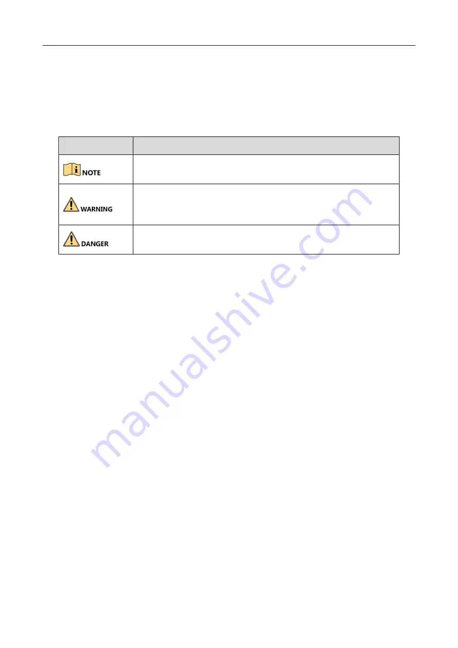
The symbols that may be found in this document are defined as follows. 

Safety Instruction 

Laws and Regulations 

Use of the product must be in strict compliance with the local laws and regulations. Please shut 
down the device in prohibited area. 

Power Supply


Use of the product must be in strict compliance with the local electrical safety regulations. 


Use the power adapter provided by qualified manufacturer. Refer to the product specification 
for detailed power requirements. 


It is recommended to provide independent power adapter for each device as adapter 
overload may cause over-heating or a fire hazard.   


Make sure that the power has been disconnected before you wire, install, or disassemble the 
device.   


DO NOT directly touch exposed contacts and components once the device is powered up to 
avoid electric shock. 


DO NOT use damaged power supply devices (e.g., cable, power adapter, etc.) to avoid electric 
shock, fire hazard, and explosion.


DO NOT directly cut the power supply to shut down the device. Please shut down the device 
normally and then unplug the power cord to avoid data loss. 


DO NOT block the power supply equipment to plug and unplug conveniently. 


Make sure the power supply has been disconnected if the power adapter is idle. 

Symbol 

Description 


Provides  additional  information  to  emphasize  or  supplement 
important points of the main text. 


Indicates  a  potentially  hazardous  situation,  which  if  not  avoided, 
could  result  in  equipment  damage,  data  loss,  performance 
degradation, or unexpected results. 


Indicates a hazard with a high level of risk, which if not avoided, will 
result in death or serious injury. 

Содержание DS-TME401-TPC

Страница 1: ...Entrance Exit Station Quick Start Guide Scan the QR code for User Manual...

Страница 2: ...UAL AND THE PRODUCT DESCRIBED WITH ITS HARDWARE SOFTWARE AND FIRMWARE ARE PROVIDED AS IS AND WITH ALL FAULTS AND ERRORS HIKVISION MAKES NO WARRANTIES EXPRESS OR IMPLIED INCLUDING WITHOUT LIMITATION ME...

Страница 3: ...ser will be required to correct the interference at his own expense FCC conditions This device complies with part 15 of the FCC Rules Operation is subject to the following two conditions 1 This device...

Страница 4: ...t the power has been disconnected before you wire install or disassemble the device DO NOT directly touch exposed contacts and components once the device is powered up to avoid electric shock DO NOT u...

Страница 5: ...ice immediately turn off the power unplug the power cable and contact the service center If the device is abnormal contact the store you purchased it or the nearest service center DO NOT disassemble o...

Страница 6: ...12 Chapter 3 Activation and Login 14 3 1 Activate Device 14 3 1 1 Default Information 14 3 1 2 Activate via Web Browser 14 3 2 Log in 14 3 3 Log out 15 Chapter 4 Basic Operation 16 4 1 Manage IP Came...

Страница 7: ...ge the parking lot effectively and charge parking fee Peripheral devices such as capture camera barrier gate remote card reader alarm device etc can be connected to the station to realize vehicle pass...

Страница 8: ...arking charge license plate number etc 2 Reserved Reserved 3 Taking ticket button Press the button to take ticket when the vehicle enters the parking lot 4 Ticket out exit Take ticket here to enter th...

Страница 9: ...nce Exit Station Quick Start Guide 8 No Name Description 8 MIC For two way audio with the management center 9 QR code scanning area Scan the payment QR code on your mobile phone to pay for the parking...

Страница 10: ...ation base should not be smaller than 400 Depth 500 Length 350 Width mm The surface should be horizontal Bury bolts before you start the installation 2 1 2 Lay Power Cord Lay the power cord from the p...

Страница 11: ...land Figure 2 1 Install Expansion Screws Step 3 Unlock the station back cover with key and lift the cover softly to open it Key Hole Back Cover Figure 2 2 Open Back Cover Step 4 Adjust the horizontal...

Страница 12: ...tation Cabinet 2 3 Wiring 2 3 1 Connect to Perihperal Devices The station can connect to control terminal and barrier gate The control terminal can manage capture display passing and payment Here we t...

Страница 13: ...Lim it G N D StationInte rnalVehi cle Detector Lock Rise Stop Fall Unl ock Risi ng Control Risi ng Control Stopping Control Stopping Control Fall ing Control Fall ing Control Fall ing Limit Output Ris...

Страница 14: ...Entrance Exit Station Quick Start Guide 13 Air switch connecting to power supply Figure 2 5 Power Connection Step 2 Reinstall the back cover and lock the cabinet...

Страница 15: ...P address of the station in the address bar of the web browser and press the Enter key to enter the activation interface Step 2 Enter a new password and confirm it Step 3 Click OK to activate the stat...

Страница 16: ...ace Step 3 Enter User Name and Password Step 4 Click Login Figure 3 1 Login Interface Step 5 Install the plug in before other operations Please follow the installation prompts to install the plug in C...

Страница 17: ...Camera Management IP Camera Step 2 Click Add Figure 4 1 Add IP camera Step 3 Enter IP Camera Address Management Port User Name and Password of the IP camera Step 4 Confirm the password Step 5 Click OK...

Страница 18: ...k OK to add it 4 1 3 Edit IP Camera You can edit the added IP camera parameters Step 1 Go to Configuration System Camera Management IP Camera Step 2 Check the camera to edit Step 3 Click Modify Figure...

Страница 19: ...llowing parameters according to your needs LCD Default Prompt Enter the information to show on LCD of the station Link Enrollment Station Ticket to Inductive Loops If it is checked when the inductive...

Страница 20: ...ticket can be taken If you select Link when there is no available parking space the vehicle cannot enter Keep Barrier Arm Raised for Tailing Vehicle If you enable the function the barrier arm will no...

Страница 21: ...Exit Settings Multi Channel Capture Figure 4 6 Multi Channel Capture Step 2 Check Multi Channel Capture to enable the function Step 3 Enter Matching Time Matching time is the longest matching waiting...

Страница 22: ...t Figure A 1 Line Bank Left GND W0 W1 A GND B AI1 12V GND 12V W1 F F W0 G Vehicle Detector Output GND Alarm Input Wiegand Figure A 2 Line Bank Right Refer to Table 4 1 for the interface description of...

Страница 23: ...rier gate interfaces to control barrier gate 24 W1 9 Fall 25 W1 10 Stop 26 GND 11 Common 27 A Vehicle detector inductive loops input 12 Rising Limit 28 B 13 Falling Limit 29 GND 14 GND 30 F Vehicle de...

Страница 24: ...Entrance Exit Station Quick Start Guide 23 UD16423B...

Отзывы: