Note:
The supplied screw package contains self-tapping
screws, and expansion bolts.
5.
Route the cables through the cable hole, or the side
opening.
6.
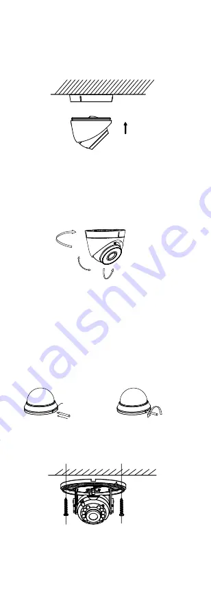
Install the camera back to the mounting base and
secure it.
Figure 2-10
Install the Camera Back
7.
Connect the corresponding cables, such as power
cord, and video cable.
8.
Power on the camera to check whether the image
on the monitor is gotten from the optimum angle. If
not, adjust the camera according to the figure below
to get an optimum angle.
Tilt Position
[0°to75°]
Rotation Position
[0° to 360°]
Pan Position
[0° to 360°]
Figure 2-11
3-Aixs Adjustment
2.4
Installation of Type VI Camera
Before you start:
The installation of ceiling mounting and wall mounting
are similar. Following takes ceiling mounting as an
example.
1.
Drill the screw holes and cable hole (optional) on
the ceiling.
2.
Align the triangle marks then pry the bubble by
anti-clockwise rotating a flat blade screwdriver.
Triangle Mark
Flat Blade
Screwdriver
Flat Blade
Screwdriver
Figure 2-12
Pry the Bubble
3.
Attach the mounting base to the ceiling with PA × 25
screws.
Figure 2-13
Attach the Mounting Base
4.
Route the cables through the cable hole, or the side
opening.
5.
Connect the corresponding cables.
6.
Power on the camera to check whether the image
on the monitor is gotten from the optimum angle. If
not, adjust the camera according to the figure below
to get an optimum angle.


