background image

SC7000 Series Smart Camera User Manual 


25


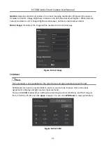
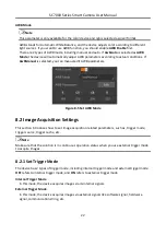
Level High: The level high of the trigger signal is valid. As long as the trigger signal is in level high, 
the device is in image acquisition status. 

Level Low: The level low of the trigger signal is valid. As long as the trigger signal is in level low, the 
device is in image acquisition status. 

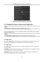
Set Trigger Delay 

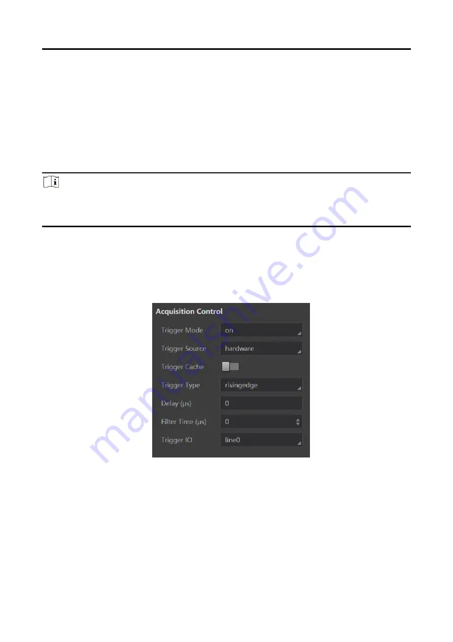
The trigger delay function allows the device to add a delay between the receipt of trigger signal 
and the moment the trigger becomes active. The range of this parameter is from 0 to 1000000 μs. 

Note 

This parameter is available only when selecting rising or falling edge as the trigger type. If level 
high or level low is selected as the trigger type, you can set trigger start delay or end delay 
according to actual demands. 
 

Set Filter Time 

The external trigger input signal of the device may have signal bounce that may cause false trigger. 
Thus, it is necessary to set filter time. The range of this parameter is from 0 to 1000000 μs. 


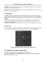
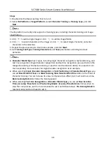
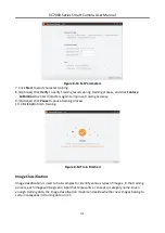
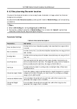
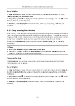
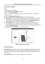
Figure 8-8 Set Related Parameters about External Trigger Mode 

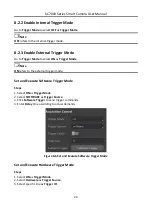
8.2.5 Enable Communication Trigger Mode 

The device also supports triggering by receiving communication string. 
Select ON as Trigger Mode, select COMMUNICATION as Trigger Source, and enter String and 
Delay according to actual demands. 

Содержание SC7000 Series

Страница 1: ...SC7000 Series Smart Camera User Manual ...

Страница 2: ...ILL HIKROBOT BE LIABLE TO YOU FOR ANY SPECIAL CONSEQUENTIAL INCIDENTAL OR INDIRECT DAMAGES INCLUDING AMONG OTHERS DAMAGES FOR LOSS OF BUSINESS PROFITS BUSINESS INTERRUPTION OR LOSS OF DATA CORRUPTION OF SYSTEMS OR LOSS OF DOCUMENTATION WHETHER BASED ON BREACH OF CONTRACT TORT INCLUDING NEGLIGENCE PRODUCT LIABILITY OR OTHERWISE IN CONNECTION WITH THE USE OF THE PRODUCT EVEN IF HIKROBOT HAS BEEN ADV...

Страница 3: ... This equipment generates uses and can radiate radio frequency energy and if not installed and used in accordance with the instruction manual may cause harmful interference to radio communications Operation of this equipment in a residential area is likely to cause harmful interference in which case the user will be required to correct the interference at his own expense Reorient or relocate the r...

Страница 4: ...ry to your supplier or to a designated collection point For more information see http www recyclethis info Symbol Conventions The symbols that may be found in this document are defined as follows Symbol Description Danger Indicates a hazardous situation which if not avoided will or could result in death or serious injury Caution Indicates a potentially hazardous situation which if not avoided coul...

Страница 5: ...d dusty environment corrosive environment or high humidity environment Do not aim the product lens at objects of strong light such as the sun and incandescent lamp Otherwise the lens may be damaged The product should be stored in dry environment without corrosive gas Avoid placing the product in direct sunlight and poorly ventilated locations or near heat sources such as heater or heating ignoring...

Страница 6: ...s can be maintained by user please do not disassemble the device arbitrarily Cleaning Please do not touch the image sensor directly If the sensor needs to be cleaned please use a clean rag and wet it with alcohol then gently wipe off the dirt if the camera is not in use please cover the image sensor with dust cover for protection Installation Please do not install the product on vibrating surface ...

Страница 7: ... 7 4 4 Output Wiring 7 4 5 RS 232 Serial Port 8 Chapter 5 Installation 10 5 1 Installation Preparation 10 5 2 Install Device 10 Chapter 6 Access Device via Web Browser 13 6 1 Search Device via Camera Search Tool 13 6 2 Access via Web Browser 13 Chapter 7 Web Operation 15 7 1 Log in 15 7 2 Forget Password 16 Chapter 8 Solution Settings 18 8 1 Camera Settings 18 8 1 1 Set Frame Rate 18 8 1 2 Set Gai...

Страница 8: ...anual Focus 27 8 4 Tool Settings 28 8 4 1 Deep Learning Training Tool 29 8 4 2 Deep Learning Character Location 33 8 4 3 Deep Learning Classification 34 8 4 4 Deep Learning Object Detection 35 8 4 5 Deep Learning Character Recognition 36 8 4 6 Image Savings 37 8 4 7 Feature Matching 38 8 4 8 Fixture Settings 41 8 4 9 Blob 42 8 4 10 Color Conversion 44 8 4 11 Format Tool 46 8 4 12 Logic Tool 46 8 4...

Страница 9: ... 63 10 1 2 Set Technician Permission and Password 63 10 2 Image Saving Management 64 10 3 Test Library Management 65 10 4 Display Settings 65 10 5 Synchronize Time 66 10 6 System Maintenance 66 10 7 View Log 68 10 8 View System Version 68 Chapter 11 FAQ Frequently Asked Question 69 11 1 Why the camera search tool cannot list cameras 69 11 2 Why the image is not clear during live view 69 11 3 Why t...

Страница 10: ...stry etc 1 2 Feature Built in vision tool of deep learning to achieve the character and object recognition and object sorting Supports automatic semi automatic focus to get clearer images Adopts high speed and large capacity memory medium for saving images Supports multiple communication modes Adopts multiple IO interfaces for input and output signals Adopts independently controlled light sources ...

Страница 11: ...SC7000 Series Smart Camera User Manual 2 Chapter 2 Appearance Figure 2 1 Appearance Type I Figure 2 2 Appearance Type II ...

Страница 12: ...ds to tighten connection between the device and cable and thus avoiding influence caused by vibration 6 12 Pin Interface It provides power input output and serial port signal The interface is designed with screw threads to tighten connection between the device and cable and thus avoiding influence caused by vibration 7 PWR Indicator It is the power indicator The indicator is solid blue when the de...

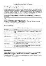
Страница 13: ... Power supply ground 3 OPTO_OUT0 Line3 signal line Opto isolated output 3 4 OPTO_OUT1 Line4 signal line Opto isolated output 4 5 OPTO_OUT2 Line5 signal line Opto isolated output 5 6 OUT_COM Line3 4 5 signal ground Common ended output 7 OPTO_IN0 Line0 signal line Opto isolated input 0 8 OPTO_IN1 Line1 signal line Opto isolated input 1 9 OPTO_IN2 Line2 signal line Opto isolated input 2 10 IN_COM Lin...

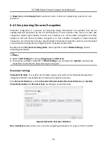
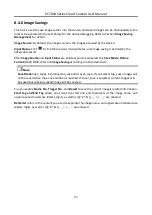
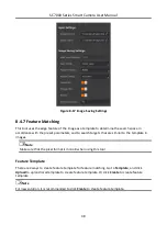
Страница 14: ...interval 200 to 300 ms Slow flashing Flashing interval 1000 ms Super slow flashing Flashing interval 2000 ms Table 3 3 Description Device Status PWR Indicator LNK Indicator ACT Indicator U1 U2 The device is powered off The device is powered on Solid blue Solid green Slow fast flashing yellow U1 is unlit and U2 is slow flashing blue Power supply exception Unlit Network exception Solid blue Unlit U1...

Страница 15: ...tage ranges from 5 VDC to 30 VDC Figure 4 1 Internal Circuit of Input Signal 4 2 Output The device s Line 3 4 5 is opto isolated output and their internal circuit is as follows Note The input voltage ranges from 5 VDC to 30 VDC The maximum current is 200 mA Do not directly connect with inductive load e g DC motor etc when outputting Figure 4 2 Internal Circuit of Output Signal ...

Страница 16: ...g to PNP Device NPN Device If the VCC of NPN device is 12 VDC or 24 VDC it is recommended to use 1 KΩ pull up resistor Input Signal Device Power PWR Device Power Ground NPN Device NPN Device Power NPN Power Ground Signal Line VCC GND Figure 4 4 Input Signal Connecting to NPN Device 4 4 Output Wiring The device can output signal to external device via I O interface and here we take type I device Li...

Страница 17: ...is 12 VDC or 24 VDC it is recommended to use 1 KΩ pull up resistor Output Signal Device Power PWR Device Power Ground NPN Device NPN Device Power NPN Power Ground Signal Line VCC GND Figure 4 6 Output Signal Connecting to NPN Device 4 5 RS 232 Serial Port The 9 pin male connector and 25 pin male connector are commonly used serial ports as shown below You can refer to the table below for the specif...

Страница 18: ...2 RX Receive data 3 TX Send data 5 GND Signal ground 25 Pin Interface 2 TX Send data 3 RX Receive data 7 GND Signal ground You can refer to the serial port wiring below to connect the device with an external device Device Power PWR Device Power Ground External Device GND RS 232 Serial Port Output TX RS 232 Serial Port Input RX GND Figure 4 9 RS 232 Serial Port Wiring ...

Страница 19: ...o C mount lens that you need to purchase it separately The lens is used for the type II device 5 Light Source 1 It is used to provide light during image acquisition You need to purchase separately The light source is used for the type II device 6 Fixed Bracket 1 It is used to fix the device You need to purchase it separately 7 M4 Screw 4 It refers to the supplied M4 screw that is used to fix the d...

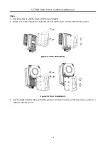
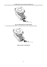
Страница 20: ...he fixed bracket 2 Select one of the installation methods and install the device to the installation position Figure 5 1 Rear Installation Figure 5 2 Front Installation 3 Use the GigE network cable with RJ45 aviation connector to connect the device to a switch or a network interface card ...

Страница 21: ...SC7000 Series Smart Camera User Manual 12 Figure 5 3 Gigabit Ethernet Interface Wiring 4 Use the power and I O cable to connect the device to a DC switch power supply Figure 5 4 Power and I O Wiring ...

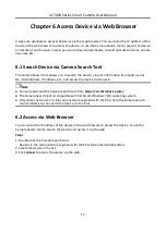
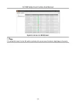
Страница 22: ...s IP address etc and access the device via the web Note You can download the Camera Search tool from https en hikrobotics com The Camera Search tool is compatible with 32 64 bit Windows 7 10 operating system Only when the device is in the same network segment with the PC where the Camera Search tool installed you can search the device via the tool 6 2 Access via Web Browser You can enter the IP ad...

Страница 23: ...SC7000 Series Smart Camera User Manual 14 Figure 6 1 Access via Web Browser Note The default browser in your PC will be opened and you can see the device login page in the web ...

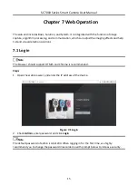
Страница 24: ...fects and help to build visual detection solutions 7 1 Log in Note The browser should support HTML5 and Chrome is recommended Steps 1 Open the web browser and enter the IP address of the device Figure 7 1 Login 2 Check Admin enter password and click Login Note The default password of admin is Abc1234 When logging in for the first time we highly recommend you to change the password in accordance wi...

Страница 25: ...nt interface Figure 7 3 User Management Interface Note You can enable Technician Permission to log in as the technician The default password of the technician is Abc1234 7 2 Forget Password If you forget the admin password you can follow steps below to reset your password Steps 1 Click Forget Password to view device serial number ...

Страница 26: ...ra User Manual 17 Figure 7 4 Forget Password 2 Mail to the technical support personnel to get the corresponding resetting file 3 Click Import to import the resetting file 4 Set a new password according to the interface prompt ...

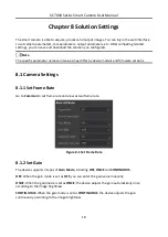
Страница 27: ...y device models and firmware versions 8 1 Camera Settings 8 1 1 Set Frame Rate Go to Common to set frame rate and view actual frame rate Figure 8 1 Set Frame Rate 8 1 2 Set Gain The device supports 3 types of Gain Mode including OFF ONCE and CONTINUOUS OFF When the gain mode is set as OFF you can enter the gain value manually ONCE When the gain mode is set as ONCE the device adjusts the gain autom...

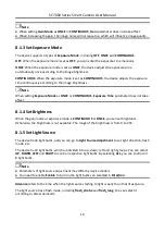
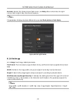
Страница 28: ...xposure Time parameter does not take effect 8 1 4 Set Brightness When the gain mode or exposure mode is CONTINUOUS or ONCE you can set brightness Otherwise the brightness is not available The range of the brightness is from 0 to 255 8 1 5 Set Light Source The device has 8 light bulbs and you can go to Light Source Adjustment to set light direction flash mode etc The device has 8 light bulbs which ...

Страница 29: ...mat The mono device supports Mono 8 only and the color device supports Mono 8 and RGB Width It refers to the image width and you can adjust it according to actual demands Height It refers to the image height and you can adjust it according to actual demands Width Deviation and Height Deviation It indicates the starting location of the upper left corner of the ROI area that is the deviation in the ...

Страница 30: ...ed the image will be reversed in a horizontal way Figure 8 3 Set Image CCM Reset Note This parameter is only available for the color device and rgb is selected as pixel format CCM stands for Color Correction Matrix and it is used to help improve inter instrument agreement in display and light sources measurements You can click Edit to adjust R G and B value according to actual conditions and their...

Страница 31: ...B parameters Figure 8 5 Set AWB Mode 8 2 Image Acquisition Settings This section introduces how to set image acquisition related parameters such as trigger mode trigger source trigger cache etc Note Make sure that the solution is in continuous operation status when you use external trigger mode to acquire images 8 2 1 Set Trigger Mode The device has 2 types of trigger mode including internal trigg...

Страница 32: ...r Mode Note ON refers to the external trigger mode Set and Execute Software Trigger Mode Steps 1 Select ON as Trigger Mode 2 Select SOFTWARE as Trigger Source 3 Click Software Trigger to send trigger commands 4 Enter Delay time according to actual demands Figure 8 6 Set and Execute Software Trigger Mode Set and Execute Hardware Trigger Mode Steps 1 Select ON as Trigger Mode 2 Select Hardware as Tr...

Страница 33: ...et Trigger Cache After enable Trigger Cache if the device receives a new trigger signal it will save and process the signal during the triggering process Trigger cache can save up to 3 trigger signals Set Trigger Type The device supports trigger acquisition in the rising edge falling edge level high or level low of the external signal Rising Edge It means that when the level signal sent by externa...

Страница 34: ...0000 μs Note This parameter is available only when selecting rising or falling edge as the trigger type If level high or level low is selected as the trigger type you can set trigger start delay or end delay according to actual demands Set Filter Time The external trigger input signal of the device may have signal bounce that may cause false trigger Thus it is necessary to set filter time The rang...

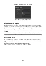
Страница 35: ...nual adjustment you are recommended to use larger focus step to adjust focus first and then use small focus step Note Make sure that the test mode is disabled and the image is in camera mode before adjusting focus automatically or manually Regarding the image mode refer to section Operate Image for details 8 3 1 Set Auto Focus Go to Focus Control to select once as Focus Mode and the device will au...

Страница 36: ...djust lens in forward direction according to the Focus Step and Focus Speed you set If click Operate in Focus Negative the device will adjust lens in backward direction according to the Focus Step you set 3 Select different focus positions from Focus Position from Position 1 to Position 8 and click Operate in Save Focus Position to save them 4 Optional After saving click Operate in Load Focus Posi...

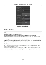
Страница 37: ...ion tools for DL character location DL classification DL object detection DL character recognition feature matching fixture blob etc After tool adding you can set their corresponding parameters save and download solutions ROI Settings For most tools you need to set image source and ROI area in basic parameter interface before setting specific operating parameters Image source is the images acquire...

Страница 38: ...ncompleteness caused by the artificially designed features Note The tool of DL character location DL classification DL object detection and DL character recognition has corresponding model files by default You can also use the deep learning training tool to create new model files according to actual demands You can download the Deep Learning Tool V1 1 0 from https en hikrobotics com The PC should ...

Страница 39: ...positioning and text line recognition Single character recognition and text line recognition are used to train the recognition ability while text positioning is used to train the location ability You need to train them separately Here we take the single character recognition as an example When selecting Single Character Recognition or Text Positioning as Character Model Type you can set Max Iterat...

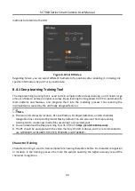
Страница 40: ... accuracy 9 Optional Click Pause to pause training process 10 Click End to finish training Figure 8 14 Train Finished Image Classification Image classification is used to train samples for identify various types of images In the training process each image will be given a label that represents a concept or category name Given enough training data the image classification model can decide whether n...

Страница 41: ...ve parameters according to actual demands Note Max Iteration Time refers to the times of image classification training You can increase its value to improve train effect but it will cost more time Basic Learning Rate determines the training speed Model Capacity has 2 types including Normal and High Accuracy and you can select it according to actual demands Figure 8 15 Set Parameters 6 Click Start ...

Страница 42: ...for the character location box Its range is from 0 01 to 0 99 Overlap Rate It refers to the overlap rate of character location boxes Its range is from 0 01 to 1 Link Threshold This parameter sets the ability to link single character location box to form a location box for text lines The larger the value and it is harder to form a location box for text lines Its range is from 0 01 to 1 Sort Type It...

Страница 43: ... judgment It has been widely applied into object recognition and sorting Double click the DL Classification select specific model in Model Settings and set operating parameters Note Refer to ROI Settings for setting Image Input and ROI Area This tool has a default model file in Model Settings You can also click Upload to upload new model files created by the deep learning training tool Parameter S...

Страница 44: ...arameter Description Parameters Description Max Number to Find It refers to the max quantity of objects to be searched Its range is from 1 to 100 Min Confidence It refers to the min score for target objects Its range is from 0 01 to 0 99 Max Overlap Rate It refers to the max overlap rate of two target objects Its range is from 0 01 to 1 Angle Enable It sets the relative angle range tolerance for t...

Страница 45: ... character recognition tool together with character location tool Double click the DL Character Recognition select specific model in Model Settings and set operating parameters Note Refer to ROI Settings for setting Image Input and ROI Area This tool has a default model file in Model Settings You can also click Upload to upload new model files created by the deep learning training tool Parameter S...

Страница 46: ...uld select the Save Mode Picture Format RAW BMP JPG and Image Saving according to actual demands Note Save Mode has 2 types including stop_save and cover_save If you select stop_save images will not be saved when max save number is reached If cover_save is selected current images will be saved but previous saved image will be covered You can enable Frame No Trigger No and Result to save the curren...

Страница 47: ...rs and to search targets that are similar to the template in images Note Make sure that the pixel format is mono 8 when using this tool Feature Template There are 2 ways to create feature template for feature matching Go to Template and click Upload to upload local template to create feature template Or click Create to create feature template Note For new solution it is recommended to click Create...

Страница 48: ...djust Scale The larger the feature scale the sparser the extracted feature edge points are Threshold Mode refers to the gray value difference between the feature point and the surrounding background and it includes manual and auto modes Under auto mode the device will automatically adjust Under manual mode you can manual set its range between 0 and 255 in Contrast Threshold 7 Optional Click to dow...

Страница 49: ... the image When the searched target displayed at the edge of the image is incomplete you can use this parameter to find the image Sort You can specify the order in which the target is searched Overtime Control When the time exceeds the time set by overtime control the search will stop and no search result will be returned If it is set as 0 the overtime control function is disabled Threshold Type I...

Страница 50: ...t text s color front size transparency position X and position Y 8 4 8 Fixture Settings Fixture is a tool for assisting the positioning and correcting the target motion deviation The position deviation reference can be set up according to the matching point and the matching frame angle in the template matching result Then the coordinate and rotation deviation of ROI detection frame can be realized...

Страница 51: ...r than Background Darker than Background means that the feature image pixel value is lower than the background pixel value Brighter than Background means that the feature image pixel value is higher than the background pixel value Note This parameter takes effect when selecting Single Threshold or Auto Threshold as Threshold Method Searching Quantity It searches the quantity of Blob image Min Size...

Страница 52: ...t It includes Grade Up Grade Down and Not Grade Connectivity In image processing the object we are interested in is usually a combination of interconnected pixels Therefore in order to obtain an area we must calculate all the connected areas that are contained in the area after division On a rectangular pixel grid there are two definitions of connectivity The first one is that the two pixels have ...

Страница 53: ...r Y etc and enter corresponding range according to actual demands In Image Display click to display or not display Blob and detection area Click to edit OK color NG color and transparency In Show Text enable Display Text to set text s color front size transparency position X and position Y Note After applying Blob tool you can view and select output results in the image display area Refer to secti...

Страница 54: ...299r 0 587g 0 114b r stands for the gray value of the R channel g stands for the gray value of the G channel and b stands for the gray value of the B channel Average Ratio r g b 3 Channel Min Min r g b Channel Max Max r g b User Ratio You can enter R G B conversion ratio according to actual demands R Channel r 0 g 0 b B Channel 0 r 0 g b G Channel 0 r g 0 b If RGB2HSV or RGB2HSI is selected as Con...

Страница 55: ...xception may occur In display interface enable Display Text to set text s color front size transparency position X and position Y Figure 8 24 Format Tool 8 4 12 Logic Tool This tool allows you to select different logical operation types and execute logic operation Select AND OR NOT NAND or NOR as Logical Operation Type and click to link data source or enter data directly You can also click to add ...

Страница 56: ... Value Decreased Value and Comparison Type according to actual demands Note If you select Full as Comparison Type only when characters are same with Standard Value and OK will be output If Range is selected as Comparison Type when characters are within the range of Increased Value and Decreased Value OK will be output If you select custom as Field Classification and the Standard Value is not numbe...

Страница 57: ...to select different communication tools according to actual demands 8 5 1 UDP In basic parameter interface set output information as Input Variable and enter Local IP Local Port Target IP and Target Port according to actual demands Note Input Variable currently supports format result data only In display interface enable Display Text to set text s color front size transparency position X and posit...

Страница 58: ...rmation as Input Variable and enter Target IP and Target Port according to actual demands Note Input Variable currently supports format result data or result of other communication tools In display interface enable Display Text to set text s color front size transparency position X and position Y Figure 8 28 TCP Client ...

Страница 59: ...Text to set text s color front size transparency position X and position Y Figure 8 29 TCP Server 8 5 4 Serial In basic parameter interface set output information as Input Variable and enter Serial Port Mode Baud Rate Parity Bit and Stop Bit according to actual demands Note Data Bit is 8 by default and it can be read only Input Variable currently supports format result data or result of other comm...

Страница 60: ...that once the device exposures and acquires images the device will output data Note If exp_event is selected as Output Type you can set advance time of exposure in Advance The Advance parameter may differ by device models Output Condition It links the results of previous module Note If exp_event is selected as Output Type Output Condition and Cache Enable are unavailable Duration refers to the dur...

Страница 61: ...s Input Status When using FTP as communication tool you need to set target IP target port user name password image saving frame index result start tag and end tag and separator according to actual solution demands Table 8 4 Parameter Description Parameters Description Target IP and Port It refers to the IP and Port of FTP server User Name Enter user name to log in FTP Password Enter password to lo...

Страница 62: ...n enter lowercase and uppercase letter digit and _ FTP Connection Detection You can click Connection Detection to detect FTP connection status Figure 8 32 FTP 8 5 7 Modbus Modbus is a communication protocol developed by Modicon systems In simple terms it is a method used for transmitting information over serial lines between electronic devices The device requesting the information is called the Mo...

Страница 63: ...ntrol Settings Add Space It is holding_register by default Add Deviation It refers to the address deviation and ranges from 0 to 900 Data Quantity It is 2 by default Status Settings Add Space It is input_register by default Add Deviation It refers to the address deviation and ranges from 0 to 900 Data Quantity It is 2 by default PLC Input Settings Add Space It is input_register by default Add Devi...

Страница 64: ...d position Y 8 5 8 Profinet Profinet is an industry technical standard for data communication over industrial Ethernet designed for collecting data from and controlling equipment in industrial systems with a particular strength in delivering data under tight time constraints In basic parameter interface you should enter Device Name according to actual demands ...

Страница 65: ...amounts of data at speeds of 10 Mbps or 100 Mbps and at up to 1500 bytes per packet It is an application layer protocol and is especially popular for control applications After completing settings in PLC Programmable Logic Controller you can use the Ethernet IP communication to link the result data and run the solution continuously Figure 8 35 Ethernet IP In display interface enable Display Text t...

Страница 66: ...gger Mode is OFF If you have enabled technician permission you can check All in Permission Assignment to open all modules to technician or check specific ones to assign them to technician Note You need to go to System User Management Technician Technician Permission to enable technician permission first In Solution Result if you have used a logic tool in your solution you can view and link the res...

Страница 67: ...SC7000 Series Smart Camera User Manual 58 Figure 8 36 Solution Completion ...

Страница 68: ... the result of all modules operation and calculation If the result is 0 the system displays NG Otherwise the system displays OK When logic tool is selected the system displays the result of logic tool you selected 9 2 View Solution Status The solution operation information module records and displays the solution name running time detection quantity and NG quantity in real time You can view and ed...

Страница 69: ...atus 9 3 Manage Solution The solution management module can set and switch among multiple solutions Figure 9 3 Manage Solution Table 9 2 Icon Description Icon Description You can search the solution here if there are many solutions Click it to upload local solutions to the device Click it to create a new solution Click it to execute the selected solution Click it to download the current solution t...

Страница 70: ...witches solution via communication string Go to Output to select communication tool to receive strings and set related parameters DI COMM refers to use both digital IO and communication string to switch solution OFF refers to disable solution switch function 9 4 View Camera Info In device information area you can view the device serial number MAC address subnet mask firmware and edit user ID or IP...

Страница 71: ...ncludes camera mode and test mode and the default image mode is camera mode If you enable Image Test in the test library it will display test mode Refer to section Test Library Management for details Click it to download the image to the PC The default format is JPG Click it to zoom out the displayed image It displays the current image scaling ratio Click it to zoom in the displayed image Click it...

Страница 72: ...o user management module If you log in as technician there is no this module The admin can access to all operation and tool modules via web and assign module operation permission to technician while technician can access to and set module parameters assigned by the admin only The default admin password is Abc1234 Click User Management enter Old Password New Password Confirm Password and Click OK N...

Страница 73: ... check Assign Permission to Technician in respective module to assign module operation permission to technician or go to Solution Others Permission Assignment to assign permission to the technician Figure 10 2 Set Technician Permission and Password 10 2 Image Saving Management Image saving management allows you to search delete download and import images that are saved via the image saving tool Yo...

Страница 74: ...t library After importing images you can select image types click Search to search images or click Reset to reset image types You can enable All to let all searched imaged be used as test images or enable images separately to be used as test images After that you should enable Image Test and the device will use the images you selected to run solutions Note After Image Test is enabled the camera mo...

Страница 75: ...rver and manual mode Steps 1 Click System Time Sync 2 Select time synchronization method Click Manual select date and time from the calendar or check Sync With PC to synchronize the time of the device with that of the local PC Click NTP enter Server Add NTP Port and Interval Hour 3 Click Save Figure 10 7 Time Synchronization 10 6 System Maintenance System maintenance allows you to update firmware ...

Страница 76: ...ally jump to login interface Only the admin can update firmware and restore factory settings You can select update file from the local PC and click OK to update firmware Figure 10 8 Update Firmware If you want to restore the device to factory settings enter Admin Password and click OK Note Device solutions will be deleted after restoring defaults You may log in again and the admin password will be...

Страница 77: ...10 10 Reboot Device 10 7 View Log Log module allows you to view device and web operation records and search and download logs Figure 10 11 View Log 10 8 View System Version About and help module allows you to view the firmware version and web version ...

Страница 78: ...ndicator For specific indicator status description refer to Section Indicator Status for details 11 2 Why the image is not clear during live view Reason Focus is not adjusted properly Solution Adjust focus according to Section Focus Control Settings 11 3 Why the image is very dark Reason The brightness of light source is not enough Exposure and gain values are too small Solution Increase the brigh...

Страница 79: ...t personnel to get the corresponding resetting file After that click Import to import the resetting file and reset the admin password 11 6 How to debug the device via the tool of image saving Solution 1 Add the image saving tool and set Image Source Input Status Save Mode Picture Format and Image Saving according to actual demands 2 Go to System Image Saving select images and import them to the te...

Страница 80: ...UD20132B ...
Отзывы: