SC5000 Series Smart Camera Quick Start Guide
17
Table 7-2 Output Electrical Feature
Parameter Name
Parameter Symbol
Value
Output Logic Level Low
VL
730 mV
Output Logic Level High
VH
3.2 VDC
Output Falling Delay
TDF
6.3 μs
Output Rising Delay
TDR
68 μs
Output Falling Time
TF
3 μs
Output Rising Time
TR
60 μs
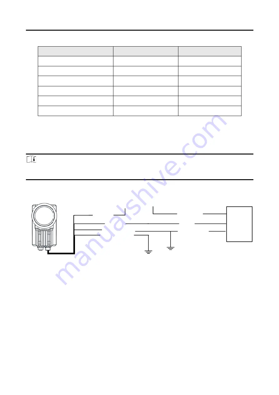
7.3 Input Signal Wiring
The device can receive external input signal via I/O interface.
Note
●
Here we take type II device as an example to introduce input signal wiring.
●
Input signal wiring may differ by external device types.
PNP Device
Opto-Isolated
Input
Device Power
PWR
Device Power Ground
PNP
Device
PNP Device Power
PNP Power Ground
Signal Line
VCC
GND of PWR
Input Signal Ground
GND of VCC
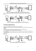
●
Figure 7-5 Input Signal Connecting to PNP Device
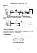
NPN Device
If the VCC of NPN device is 12 VDC or 24 VDC and pull-up resistor is not used, its wiring is as
follows.
Содержание SC5000 Series
Страница 1: ...SC5000 Series Smart Camera Quick Start Guide ...
Страница 31: ...UD26897B ...


