Intelitek ViewFlex, Assembly Instructions Manual
Discover the Intelitek ViewFlex, a state-of-the-art tech marvel revolutionizing assembly processes. Experience seamless integration with our user-friendly interface, allowing users to effortlessly follow detailed step-by-step instructions. Unlock the potential of your device with our free, downloadable Assembly Instructions Manual, available exclusively at manualshive.com.
Share
Download


Reviews:
No comments
Related manuals for ViewFlex

Holo360
Brand: Acer Pages: 18

GX-20 - Digital Camera SLR
Brand: Samsung Pages: 2

PPIC91000
Brand: Abus Pages: 20

ARTCAM-036MI2 Series
Brand: ARTRAY Pages: 20

PL1148
Brand: safer guard Pages: 7

CAMEDIA D-460 Zoom
Brand: Olympus Pages: 2

tl-1024ucl
Brand: Takex Pages: 17

EC2028-WC
Brand: Ecco Pages: 24

T20 - Advantix Auto Camera
Brand: Kodak Pages: 86
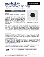
CeilingVIEW SD CCU
Brand: VADDIO Pages: 16

PY0105
Brand: Peiying Pages: 36

ROADCAM AI PLUS BT533642
Brand: Yada Pages: 29

mvBlueCOGAR-P Series
Brand: Matrix Vision Pages: 2

UVC-G3-FLEX
Brand: UniFi Pages: 42

ringflash hs 400
Brand: walimex Pages: 81

FUJINON XA55x9.5BESM-S5L
Brand: FujiFilm Pages: 72

BC950
Brand: Sercomm Pages: 30

N35110
Brand: Beward Pages: 76


