background image

35

English

NOTE

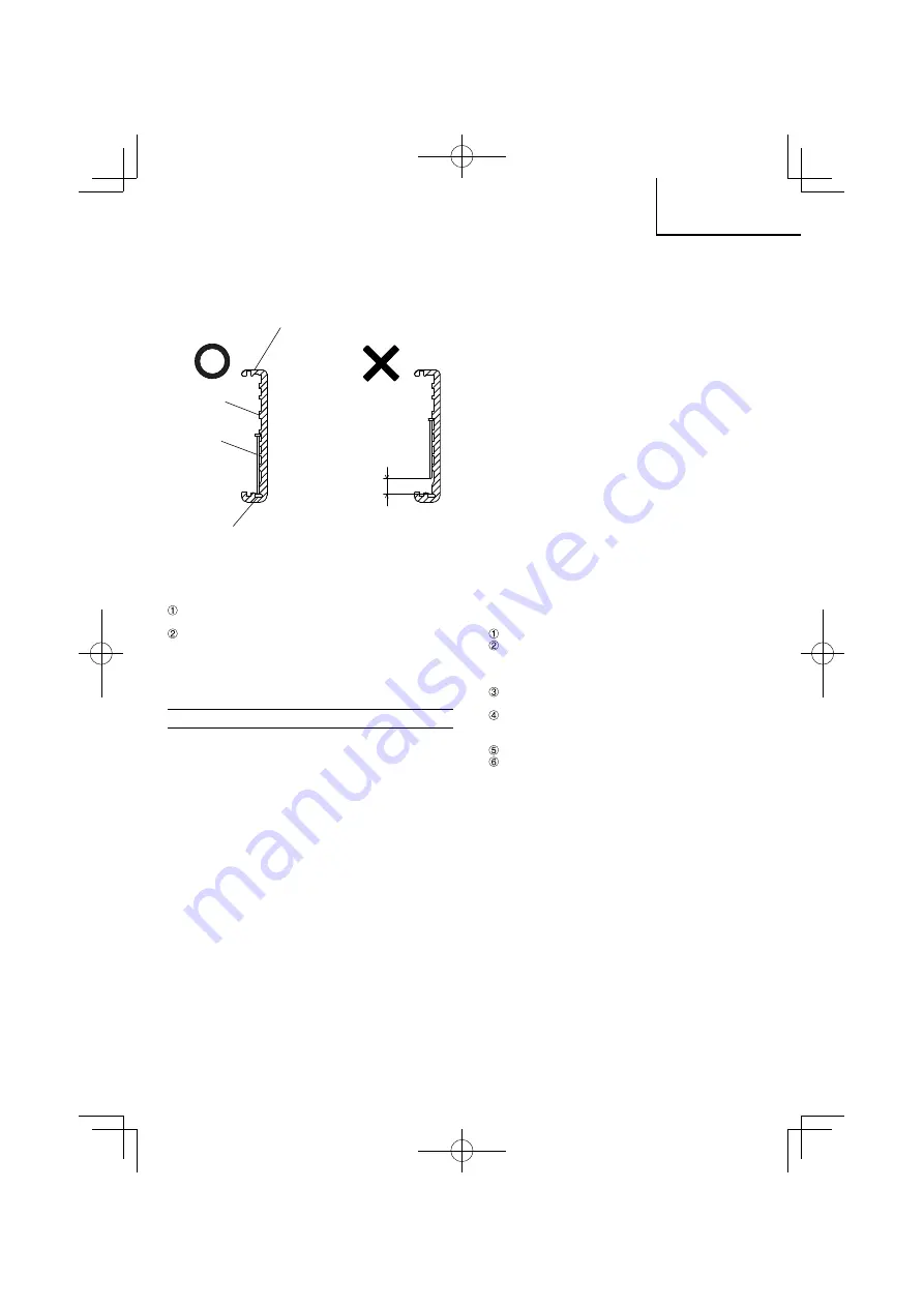
  The nails shown in page 34 can be loaded onto the side 

guide groove of the magazine without any adjustment.


Always keep the points of nails in contact with Groove.

Magazine

Gap

Side guide 

groove

Nail 

Groove

  Use nail strip of more than 5 nails.

The Nailer is now ready to operate.

Removing the nails:

 Lightly press the stop lever and gently pull out the 

magazine cover. 

  Remove the nails from the nailer.

CAUTION

  To prevent unintentional operation, never touch the 

trigger or place the top end of the push lever on a work 

bench on 

fl

 oor. Also, never face the nail outlet toward 

any part of a person.

HOW TO USE THE NAILER

CAUTION

  Do not use the body or any portion of the tool as a 

hammer as nails may be discharged unexpectedly or 

the tool may become damaged and serious injury could 

occur.

  Take precautions to ensure the safety of persons in the 

vicinity during operation.

  Ensure tool is always safely engaged on the workpiece 

and cannot slip.

  Never carry a pneumatic tool by its hose.

  Never drag a pneumatic tool by its hose.

1.   Nailing procedures


This product is a nailer using SINGLE SEQUENTIAL 

ACTUATION MECHANISM. If you pull the trigger 

fi

 rst, 

nothing will happen even if you press the push lever up 

against an object.


Depress the nail outlet onto the desired point; then pull 

the trigger to drive a nail in a single shot (See 

Fig. 6

).


After nailing once, nailing will not be possible again until 

the trigger is released and pressed again.


Don’t turn a trigger pin, it’s locked (See 

Fig. 7

).


You cannot drive a nail by 

fi

 rst pulling on the trigger 

and then pressing the push lever against an object 

(continuous nailing).

WARNING


A nail will 

fi

 re each time the trigger is depressed as long 

as the push lever remains depressed.

CAUTION

  Exercise care when nailing corners of lumber.  When 

continuous nailing corners of lumber, a nail may go 

astray or break through the corner.

  Do not drive a nail on another nail.

  Do not drive a nail on metal parts.

NOTE

  Precautions on no-load operation


Sometimes nailing will continue after driving in all nails 

previously contained in the magazine.


This is termed “no-load operation”. Such operation may 

deteriorate the damper, magazine, and nail feeder.


To avoid no-load operation, occasionally con

fi

 rm  the 

amount of remaining nails. On the other hand, all nails 

should be removed after using this nailer.

  Always handle nails and package carefully. If nails are 

dropped, collating bond may be broken.

 After nailing:

(1)  disconnect air hose from the nailer;

(2)  remove all nails from the nailer;

(3) supply 5 – 10 drops of HiKOKI pneumatic tool 

lubricant into the air plug on the nailer; and 

(4) open the petcock on the air compressor tank to 

drain any moisture.

2.  Adjusting the nailing depth (See Fig. 8)


To assure that each nail penetrates to the same depth, 

be sure that:

(1)  the air pressure to the nailer remains constant (regulator 

is installed and working properly), and 

(2)  the nailer is always held 

fi

 rmly against the workpiece.


If nails are driven too deep or shallow into the workpiece, 

adjust the nailing in the following order.

  Disconnect air hose.

  If nails are driven too deep, turn the adjuster to the 

shallow side.


If nails are driven too shallow, turn the adjuster to 

the deep side.

  Stop turning the adjuster when a suitable position is 

reached for a nailing test.

  Connect the air hose.


Always wear eye protector.


Perform a nailing test.

  Disconnect air hose.

  Choose a suitable position for the adjuster.

3.   Changing the exhaust direction


The direction of the exhaust vent can be changed by 

turning the top cover (See 

Fig. 9

).

4.  Using the nose cap (See Fig. 10)


The nose cap is attached to the push lever tip to protect 

the workpiece from scratches or damage. Remove in 

the order shown below when not using.

(1)  DISCONNECT AIR HOSE FROM NAILER.

(2) Pull out the nose cap in the direction of the arrow as 

shown in the diagram.

  Attach to the tip of the push lever in the reverse order of 

detaching.

When not using the nose cap, attach to the storage area 

in back of the magazine (See 

Fig. 11

).

0000Book̲NT50AE2(T)̲NE.indb   35

0000Book̲NT50AE2(T)̲NE.indb   35

2019/08/13   10:12:24

2019/08/13   10:12:24

Содержание NT 50AE2 (T)

Страница 1: ...var denne manual s ledes at den er tilg ngelig for dem der anvender s mpistolen Les grundig og forst anvisningene f r bruk S rg for at denne bruksanvisningen er tilgjengelig for de som skal bruke spik...

Страница 2: ...2 1 2 3 4 5 0000Book NT50AE2 T NE indb 2 0000Book NT50AE2 T NE indb 2 2019 08 13 10 12 10 2019 08 13 10 12 10...

Страница 3: ...3 6 7 8 9 10 11 12 13 0000Book NT50AE2 T NE indb 3 0000Book NT50AE2 T NE indb 3 2019 08 13 10 12 12 2019 08 13 10 12 12...

Страница 4: ...4 14 0000Book NT50AE2 T NE indb 4 0000Book NT50AE2 T NE indb 4 2019 08 13 10 12 13 2019 08 13 10 12 13...

Страница 5: ...asin Magasin Magasin Magasinh lje Magasind kke Magasindeksel Stopparm Stoparm Stopparm Avtryckarbult Aftr kker Avtrekkerpinne Avtryckare Udl ser Avtrekker Justerare Regulator Regulator Tryck Tryk Pres...

Страница 6: ...ng Makasiini Magazine Makasiinin kansi Magazine Cover Pys ytysvipu Stop lever Laukaisimen tappi Trigger pin Laukaisin Trigger S din Adjuster Paina Press Ved Pull out Naulaliuska Nail strip Vako Groove...

Страница 7: ...utf rs av en auktoriserad serviceveombud och att endast originaldelar anv nds 12 F rvara elverktyget p l mplig plats N r elverktyget inte anv nds ska det f rvaras p en torr plats och utom r ckh ll f...

Страница 8: ...ang ende tryckarmen ocks att den aldrig f r modifieras eller monteras loss 10 Anv nd endast specificerade spikar Anv nd aldrig andra typer av spikar n de som specificeras och beskrivs i denna bruksanv...

Страница 9: ...gar snubblingar och fall r huvudorsaker till personskada p arbetsplatser T nk p att hala ytor kan orsakas genom anv ndning av verktyget och var medveten om snubbelrisken som tryckluftsslangen utg r 30...

Страница 10: ...ngden p spikarna samt h rdheten p tr materialet ifr ga Beakta noga luftkompressorns utg ende tryck kapacitet och r rledning s att lufttrycket inte verstiger angiven gr ns Observera att f r h gt tryck...

Страница 11: ...igenom kanten Driv inte i en spik i en annan spik Driv inte i en spik i metalldelar ANM RKNINGAR Att observera ang ende tomg ngsspikning Ibland kan det h nda att spikning r kar forts ttas efter att de...

Страница 12: ...ning REDUCERVENTIL MED SM RJFILTER lufts ttning F r att utrustningen ska kunna drivas under optimalt f rh llande med s l ng livsl ngd som m jligt rekommenderas att en reducerventil med sm rjfilter ins...

Страница 13: ...eds rsager Efterse v rkt jet med j vne mellemrum s ledes at det til enhver tid kan anvendes sikkerhedsm ssigt forsvarligt og e ektivt 11 Ret henvendelse til en autoriseret service agent hvis reparatio...

Страница 14: ...ejdsredskab 9 Kontroller udl serarmen inden v rkt jet tages i brug Du kan hvile v rkt jet p en vandret overflade som vist i Fig 5 S rg for ikke at p f re kraft nedad p v rkt jet i det omfang at trykh...

Страница 15: ...det tages ud af forbindelse 26 Under anvendelse af v rkt j skal operat ren indtage en passende men ergonomisk korrekt arbejdsstilling Oprethold sikkert fodf ste og undlad akavede arbejdsstillinger ell...

Страница 16: ...tc er strammet helt Kontroller at s mpistolen er fri for luftudsivning og rust Kontroller om udl serarmen fungerer som den skal Kontroller ligeledes om der har samlet sig snavs p udl serarmens bev gel...

Страница 17: ...hvorefter du kan trykke igen Drej ikke udl serpinden den er l st se Fig 7 Det er ikke muligt at s mme ved f rst at trykke p aftr kkeren og herefter trykke trykpinden mod emnet konstant s mning ADVARSE...

Страница 18: ...kal de sikkerhedsforskrifter og sikkerhedsstandarder som er g ldende i hvert land observeres KOMPRESSOR FORSIGTIG S rg for at anvende en reduktionsventil mellem luftkompressorenogs mpistolen hvisluftk...

Страница 19: ...fast grep og v r forberedt p h ndtere rekyl 15 Oppbevar elektroverkt y som ikke er i bruk utilgjengelige for barn og la aldri personer som ikke er kjent med elektroverkt yet eller denne brukerveiledn...

Страница 20: ...ranstaltninger og ke faren for skader p brukeren og eller tilskuere 12 V r forsiktig n r du kobler til slangen For unng at verkt yet g r av ved et uhell s rg for f lgende n r du kobler til slangen og...

Страница 21: ...av verkt yet samt faren for snuble for rsaket av luftslangen 30 Fortsett med ekstra forsiktighet i ukjente omgivelser Skjulte farer kan forekomme for eksempel elektrisitet eller andre brukskabler 31...

Страница 22: ...spikrene og hvor hardt treverket er som det spikres i V r spesielt oppmerksom p utgangstrykket kapasitet og r rene p luftkompressoren slik at lufttrykket ikke overstiger den spesifiserte grensen Merk...

Страница 23: ...j rnet Ikke skyt inn en spiker opp en annen spiker Ikke skyt spiker mot metalldeler MERK Forholdsregler om tomgangsbruk Noen ganger vil spikring fortsette etter at alle spiker som l i magasinet er bli...

Страница 24: ...tsomr det 4 9 8 3 bar Hvis det er installert en oljefilter reduksjonsventil er det ogs mulig sm re p en enkelt m te OLJEFILTER REDUKSJONSVENTIL For at utstyret skal kunne brukes under optimale forhold...

Страница 25: ...oja vaihto osia 12 S ilyt ty kalu oikein Kun ty kalua ei k ytet se tulee s ilytt kuivassa paikassa poissa lasten ulottuvilta Pane ty kaluun 5 10 tippaa ljy letkuliitoksesta jotta se saadaan suojattua...

Страница 26: ...itysty kaluun ei saa tehd muutoksia Muutokset voivat v hent turvatoimien tehokkuutta ja lis t k ytt j n ja tai sivullisiin kohdistuvia vaaroja 12 Ole varovainen kun liit t letkun Kun liit t letkun ja...

Страница 27: ...nnissa on otettava huomioon ty kalun k yt n aiheuttama p ly ja sen mahdollisesti nostattama olemassa oleva p ly 33 Suuntaa poistoilma siten ett se p lyisiss ymp rist iss nostattaa mahdollisimman v h n...

Страница 28: ...jen k rjet kosketuksessa vakoon Katso Kuva 3 3 Liu uta naulaliuska ter nohjaimeen Katso Kuva 4 4 Varmista ett naulaliuska on asetettu sivuohjainvakoihin ja vakoon kunnolla sitten ty nn makasiinin kant...

Страница 29: ...sta toiminnasta Joskus naulaus jatkuu senkin j lkeen kun kaikki makasiinissa olevat naulat on jo kiinnitetty T st k ytet n nimityst ilman kuormaa tapahtuva toiminta T llainen toiminta vahingoittaa pus...

Страница 30: ...mpressorin ja naulaimen v liin S d ilmanpaine sitten k ytt alalle 4 9 8 3 baaria Jos ilmas din on asennettu voitelu on my s mahdollista mik on lis mukavuus LJYSUODATTIMEN V HENNYSVENTTIILI ILMAS DIN J...

Страница 31: ...the power tool in a proper place When not in use the power tool should be kept in a dry place out of the reach of children Put into the body 5 10 drops oil through the hose joint to protect the tool...

Страница 32: ...that it must never be modified or removed 10 Use specified nails only Never use nails other than those specified and described in these instructions 11 Do not modify the fastener driving tool Modifica...

Страница 33: ...p hazards caused by the airline hose 30 Proceed with additional care in unfamiliar surroundings Hidden hazards may exist such as electricity or other utility lines 31 Make sure there are no electrical...

Страница 34: ...length of nails and hardness of the wood being nailed Pay special attention to the output pressure capacity and piping on the air compressor so that air pressure does not exceed the specified limit No...

Страница 35: ...arts NOTE Precautions on no load operation Sometimes nailing will continue after driving in all nails previously contained in the magazine This is termed no load operation Such operation may deteriora...

Страница 36: ...nstalled lubrication is also possible thus providing additional convenience OILER FILTER REDUCING VALVE Air Set So that the equipment can be operated under an optimum condition to ensure extended serv...

Страница 37: ...37 0000Book NT50AE2 T NE indb 37 0000Book NT50AE2 T NE indb 37 2019 08 13 10 12 25 2019 08 13 10 12 25...

Страница 38: ...38 0000Book NT50AE2 T NE indb 38 0000Book NT50AE2 T NE indb 38 2019 08 13 10 12 25 2019 08 13 10 12 25...

Страница 39: ...39 0000Book NT50AE2 T NE indb 39 0000Book NT50AE2 T NE indb 39 2019 08 13 10 12 25 2019 08 13 10 12 25...

Страница 40: ...Europa er bemyndiget til at kompilere den tekniske fil Erkl ringen g lder produktet der er m rket med CE EC DECLARATION OF CONFORMITY We declare under our sole responsibility that Brad Nailer identif...

Отзывы: