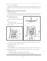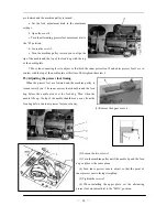
a. Turn off the power switch.
b. Loosen the screw 4, and then remove the cover 3.
c. When the red mark stops in a position over the mark on the belt cover, the needle up stop position disc 1
should be turned in the opposite direction as the direction of machine pulley rotation. When the red mark stops
in a position under the mark on the belt cover, Turn the disc 1 in the same direction as the pulley rotation
direction.
(2) Adjusting the needle down stop position
When the sewing machine stops in the needle down stop position, the black mark on the pulley should be
consistent with the mark on the belt cover A. Adjust as follows:
a. Turn off the power switch.
n a position over the mark on the belt cover, the needle down stop position
disc 2 s
ion of machine pulley rotation. When the black
mark stops
is no need to loosen the screw 5, when turning the discs.
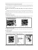
5) Lubrication
d
“FULL”. The
.
USE THE MACHINE
1) Threading
p
b. When the black mark stops i
hould be turned in the opposite direction as the direct
in a position under the mark on the belt cover, Turn the disc 2 in the same direction as the pulley
rotation direction.
c. After adjusting, install the cover 3, with screw 4.
Note: There
Before the new machine is used, please loosen the screw 2 and
full the oil into the oil case. Set the oil level between “EMPTY” an
n replace oil-filling screw 2
4. HOW TO
Raise the thread take-up lever to its highest position and thread the u per thread in the following order.
—
4
—
Содержание GC20688-BDC
Страница 24: ...A ARM BED MECHANISM 21...
Страница 28: ...B THREAD TENSION REGULATOR MECHANISM 25...
Страница 31: ...C NEEDLE BAR AND THREAD TAKE UP MECHANISM 28...
Страница 34: ...D PRESSER FOOT MECHANISM 31...
Страница 37: ...E UPPER FEED LIFTING ROCK SHAFT MECHANISM 34...
Страница 40: ...F STITCH REGULATOR MECHANISM 37...
Страница 43: ...G FEEDING AND FEED LIFTING HOOK SHAFT MECHANISM 40...
Страница 46: ...H HOOK SADDLE MECHANISM 43...
Страница 50: ...I OIL LUBRICATION MECHANISM 47...
Страница 53: ...J ACCESSORIES 50...
Страница 55: ...K PNEUMATIC CONTROL MECHANISM 52...
Страница 57: ...L KNIFFE MECHANISM 54...


