background image

HID Corporation, 9292 Jeronimo Road, Irvine, CA 92618-1905, USA  •  Tel: (949) 598-1600, (800) 237-7769, Fax: (949) 598-1690 

http://www.hidcorp.com 

MaxiProx DFM Reader Installation Manual 5375-901 Rev D 

Page 

5 of 20


Chapter 1  MaxiProx System Overview 

The MaxiProx Reader is a self-contained proximity Reader.  The two piece polycarbonate enclosure has 
an O-ring that weather seals the enclosure pieces together and a cable fitting that seals the cable entry.  
The water-resistant unit is designed for outdoor use.  The enclosure is mountable on a single gang 
electrical box. A bi-color LED and audible tone provide user feedback. Configurable open collector data 
outputs provide the data to the Host.  Configurable DIPswitches and jumpers provide choice of data 
interfaces between Wiegand,  Clock and Data, RS 232 and RS422.  The data interface is configured as 
ordered from the factory, but can be changed in the field - please contact 

HID Technical Support

 for 

assistance.  A tamper switch can alert the Host when the enclosure is opened.  Internal DIP switches 
and jumpers provide for configuration of the outputs, audible tone and LED control options.  
Installation of the MaxiProx Reader consists of mounting, connecting the cable to the Host and 
+12VDC or +24VDC power, verifying the DIPswitch and jumper settings, verifying Autotune, and 
verifying the reading of a transponder. 

1.1 

1.1   Operation

Operation   

Transponders (Proximity Cards or ProxKeys) are presented to the front of the MaxiProx. The LED is 

red


when ready to read a transponder. The LED turns 

green

 and the beeper sounds when the tra nsponder 

is read and the message is transmitted to the Host computer or interface panel. The system is ready for 
another transponder as soon as the LED returns to 

red

. There is an anti-passback delay of about one 

and a half seconds before  it will read the same card. The LED flash is typically 250 milliseconds long. 
The operation of the LED and beeper may be controlled by the Host, in which case the actual operation 
will depend on the programmed timing of the Host. 

1.2 

1.2   Parts List

Parts List   


1. 

MaxiProx Reader 

Qty 1 (included) 

2. 

Installation Manual 

Qty 1 (included) 

3. 

Cable Fitting 

Qty 1 (included) 

4. 

Label for front cover - HID logo 

Qty 1 (included) 

5. 

#6-32 x 1" flat head screw, for upper-left base mount 
screw   

Qty 1 (included) 

6. 

#6-32 x 1" black screw, for gang-box mounting 

Qty 2 (included) 

7. 

#6-32 x .75" flat head screw, for front cover mounting 

Qty 1 (included) 

8. 

Cable, 5 conductor, 22 AWG  (Alpha 1295 C or 
equivalent) 

See cable notes 

9. 

Power Supply – 2.0 A linear regulated 

+24VDC, nominal (+21 TO 28.5VDC) 
Factory Default – No P2 Shunt Jumper 
For Europe, use ALTRONIX SMP3            
(USER SUPPLIED TRANSFORMER AND 
BATTERY) 

10. 

+12VDC Shunt Jumper – P2-1 to P2-2 for 12VDC 
operation 

+12VDC, nominal (+11.6 to +20.9VDC) 
For Europe , use ALTRONIX SMP3 
(USER SUPPLIED TRANSFORMER AND 
BATTERY) 

1.3 

1.3   Regulatory Approvals and Certifications

Regulatory Approvals and Certifications  

§ 

Underwriters Laborites listing 

§ 

CE Mark 

Проектирование

Монтаж

Продажа

. - http://vskd.ru

Содержание MaxiProx 5375A

Страница 1: ...Irvine CA 92618 1905 USA Tel 949 598 1600 800 237 7769 Fax 949 598 1690 http www hidcorp com MaxiProx DFM Reader Installation Manual 5375 901 Rev D Page 1 of 20 Installation Manual 5375 901 Rev D Maxi...

Страница 2: ...WER SUPPLY 10 2 12 AUTOTUNE OPERATION 10 2 13 READER TESTING 10 2 14 POWER UP TUNE 10 2 15 PERIODIC AUTOTUNE 10 2 16 SUPERVISOR MODE 10 2 17 INSTALL COVER 10 CHAPTER 3 INSTALLATION NOTES AND GUIDELINE...

Страница 3: ...598 1690 http www hidcorp com MaxiProx DFM Reader Installation Manual 5375 901 Rev D Page 3 of 20 FIGURES FIGURE 1 MAXIPROX FRONT VIEW 11 FIGURE 2 MAXIPROX INTERIOR VIEW SHOWING MOUNTING HOLE LOCATIO...

Страница 4: ...ual 5375 901 Rev D Page 4 of 20 TABLES TABLE 1 TB1 CONNECTOR DEFINITION 7 TABLE 2 TB2 CONNECTOR DEFINITION 7 TABLE 3 DIPSWITCH AND JUMPER SETTINGS 8 TABLE 4 INTERFACE JUMPERS DESCRIPTION P3 AND P4 8 T...

Страница 5: ...Transponders Proximity Cards or ProxKeys are presented to the front of the MaxiProx The LED is red when ready to read a transponder The LED turns green and the beeper sounds when the transponder is r...

Страница 6: ...meter 40 inches to another MaxiProx 2 3 2 3 Mounting Applications Mounting Applications The MaxiProx may be mounted to a gooseneck that is 1 inch in diameter with a 4 inch diameter mounting flange wit...

Страница 7: ...ear of the MaxiProx Feed the cable through the cable fitting Connect the wires to the terminal strip with the minimum length necessary Do not leave extra loops of wire inside the Reader housing Connec...

Страница 8: ...sh after valid card read 6 Single Dual external LED Off Off single line LED control On dual line LED control 7 Serial Baud 1 control Off See baud rate chart below 8 Serial Baud 2 control Off See Baud...

Страница 9: ...e control line is necessary If ON it is in Dual Mode and the LED is normally off two control lines are necessary for host control of red and green 5 SW5 3 Terminating Resistor Some RS422 connections r...

Страница 10: ...e additional flash beep is the correct sequence for Green Flash Beep on valid read SW1 5 off Three initial green flashes and beeps followed by a pause and then one additional beep indicate no Green Fl...

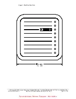
Страница 11: ...onimo Road Irvine CA 92618 1905 USA Tel 949 598 1600 800 237 7769 Fax 949 598 1690 http www hidcorp com MaxiProx DFM Reader Installation Manual 5375 901 Rev D Page 11 of 20 Figure 1 MaxiProx Front Vie...

Страница 12: ...NT TB2 9 TX TB2 8 TX 1 3 P2 5 1 TB1 9 1 TB2 P1 1 3 P4 3 1 1 3 P3 SHUNT PINS 2 AND 3 21 28 5 VDC DEFAULT SHUNT PINS 1 AND 2 11 20 VDC SW1 SW2 SW5 SW5 1 SW5 2 SW5 3 SW5 4 SW5 5 SW5 6 SW5 7 SW5 8 DATA 1...

Страница 13: ...orbs energy from the Reader excite field and affects the signal being received from the card by re directing excite field transmissions into the receiver circuitry Moving the Reader away from the meta...

Страница 14: ...ess control cards 3 4 3 4 Transponder Types Transponder Types The type of transponder used affects the read range of the MaxiProx The various styles of HID cards and transponders use different types o...

Страница 15: ...s Code Format 1 1 1 1 1 1 1 1 1 1 2 2 2 2 2 2 2 1 2 3 4 5 6 7 8 9 0 1 2 3 4 5 6 7 8 9 0 1 2 3 4 5 6 P1 C C C C C C C C C C C C C C C C C C C C C C C C P2 Parity Format 1 1 1 1 1 1 1 1 1 1 2 2 2 2 2 2...

Страница 16: ...Logic Levels Voltage Data Outputs Data0 and Data1 Control Inputs LED s Hold Beeper Levels Minimum Maximum Minimum Maximum Voh 3 5V 5 5V 3 5V 5 5V Vol 0 0V 0 5V 0 0V 0 5V Ioh 0 0mA 5 0mA 1 0mA 0 0mA I...

Страница 17: ...ed on Track 2 are 40 this product will output less than 40 characters The data consists only of BCD digits the remaining HEX digits A to F are used for the start and end sentinel data separators and c...

Страница 18: ...tripe card traveling at 8 9 inches per second The timing is to be adjustable for cards traveling at 4 inches per second to 20 inches per second This relates to bit times of 3 3 ms and 666us respective...

Страница 19: ...essage iiii LRC of nibbles aaaa to hhhh start B and end sentinel F xor of the nibbles or the even parity of the respective column The output from the Reader will look like the following 1248p 1248p 12...

Страница 20: ...ue 7 is sent as an ASCII character 7 or the hex value E is sent as an ASCII character E The CC field is reserved for use by HID Corporation The valid values are 00 through 7F The DDDDDDDDDD field is t...

Страница 21: ...ttp www hidcorp com MaxiProx DFM Reader Installation Manual 5375 901 Rev D Page 21 of 20 The checksum was computed by adding 00 01 23 4A BC DE 208 hex The checksum is the least significant 8 bits of t...

Отзывы: