Picture2.Dimensions Unit:mm
2.2.1.1
Contact Pin Interface
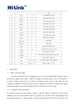
The Pin of this product as shown above is defined as follows
:
Table2-2 module pin interface
No.
Function
Direction
Explanation
1
VCC5V
A
Supply Voltage, 5V+/-10%
2
GND
GND
Analogue Ground
3
WIFILED
O
WLAN Activity LED
4
VO3.3
I
3.3V Output (Suuport Atmost 300mA)
5
LINK1
I/O
10/100 PHY Port #1 activity LED
6
N/A
Reserved
7
N/A
Reserved
8
GPIO0
General GPIO Reserved
9
GPIO1
General GPIO Reserved
10
ES/RST
I/O
Exit transparent transmission mode/Restore factory

