58
CDR-830
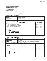
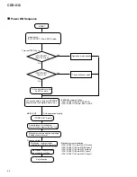
[Procedure]
1. Press the AUTO/MANUAL key and shift to the MPP Offset Readjustment.
(Press the AUTO/MANUAL key several times to appear the right indication.)
2. Monitor the TE waveform with VC.
Be careful with monitoring TE waveform instead of MPP waveform in the readjustment !
3. Adjust the JOG key so that TE offset becomes zero.
4. Press the ENTER key to register the adjustment.
6.7.8 MPP Offset Readjustment
0 mV
±
50 mV
CN102-pin 5 (Tracking err)
Test Point
Adjustment Value
Optimizing DC offset voltage of tracking-error output circuit.
Playback does not function, incapable of searching, or track jumping.
Purpose
Symptom when Out of Adjustment
Adjustment method
FL Indication
CN102
TE
VC
5
6
10: 1 prove
Oscilloscope
Содержание BurnIT CDR-830
Страница 42: ...CDR 830 42 A B C D 1 2 3 4 1 2 3 4 PNP1478 A IC404 Q405 Q404 Q403 IC801 IC405 IC601 AUDIO ASSY D SIDE B D...
Страница 45: ...CDR 830 45 A B C D 5 6 7 8 5 6 7 8 G IC701 IC702 IC706 CN601 D SIDE A SIDE B...
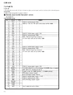
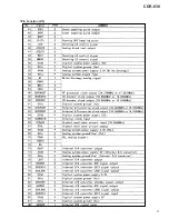
Страница 71: ...71 CDR 830 Pin Function 2 5...
Страница 72: ...72 CDR 830 Pin Function 3 5...
Страница 73: ...73 CDR 830 Pin Function 4 5...
Страница 74: ...74 CDR 830 Pin Function 5 5...
Страница 78: ...78 CDR 830 AK8567 CD R CORE PCB ASSY IC101 RF Processor Pin Function 1 2...
Страница 79: ...79 CDR 830 Pin Function 2 2...
Страница 82: ...82 CDR 830 1 FL TUBE Grid Assignment Pin Connection PEL1101 OPERATING ASSY V701 7 2 2 DISPLAY...
Страница 83: ...83 CDR 830 Anode Connection...
Страница 89: ...CDR 830 89 ORDER NO RRV2408M T ZZR DEC 2000 Printed in Japan...


