FRU Replacement Guide
4 Storage Node Replaceable Units
44
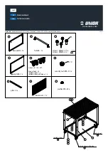
e. S2
(Storage network #2)
Figure 22: Storage Node, Back
c) At the back of the chassis, disconnect the miniSAS cables.
Unlatch the miniSAS cables by pulling very gently on their pull tabs. While pulling gently on its pull tab, grasp
its metal connector or cord to pull the cable out of its port.
Warning:
Do not pull the cable out by its pull tab, because the pull tab might break.
Observe the amber LED on the paired Storage Enclosure Basic indicating loss of connection.
d) At the back of the chassis, disconnect the two power cords.
In the image above, the power cords are connected to the PSUs labeled
P1
and
P2
.
e) At the front of the chassis, slowly slide the chassis out until you reach the
pull-safety
at the midway point (you
will hear a soft clicking sound, and feel the chassis "catch" on the rails).
f) Disengage the
pull-safety
on both sides of the chassis and slide it out until the split line of the two top covers.
Push the
pull-safety
on one side up, and the
pull-safety
on the other side down.
g) Continue to slowly slide the chassis out until you reach the
pull-safety
at the end point, and disengage it as you
did the earlier one.
h) Safely unmount the chassis from the rack and place it on a table.
Caution:
A Storage Node chassis weighs about 43lbs. Ensure that you have sufficient
manpower to handle it safely.
Warning:
Once you pull the chassis past the
pull-safety
, do not leave it hanging in the rack.
Otherwise, the rack rails may be damaged permanently.
5.
Move the two HDDs from the failed chassis to the
exact corresponding slots
in the new chassis.
Tip:
Write down the disk serial number and slot location so that you can double-check that each
disk is seated in the correct slot post installation into the new chassis.
a) Remove each disk from its slot in the front bay of the failed chassis.