


PAGE 9
© Copyright Hewland Engineering Limited 2001-2009
a) Determine the correct fixture settings to achieve the correct backlash at a given bearing pre-load.
(See illustrations on following pages)
It is assumed that the pinionshaft is fitted and set at the correct position inside the maincase.
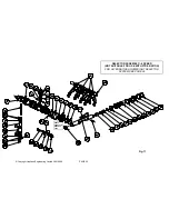
Build the differential and then press the bearing inners (7) onto the journals and mount the crownwheel onto it. Fit spacer (22) into the
maincase bearing bore, followed by a nominal amount of shim (21). A good starting point is probably 0.040”
Fit the dummy bearing outer track SK-1715 to the maincase followed by the diff assembly. Fit the second dummy bearing outer track
SK-1715 to the setting fixture and position onto the maincase. Secure the fixture to the maincase using all 12 nuts (55) and torque to
35Nm.Ensure that the pinionshaft does not run out of backlash whilst tightening the sideplate fixing nuts and add shim if necessary.
Please note that it is important to use all nuts torqued to the correct setting, as this affects backlash readings.
Fit the nut (SK-1718-A) to the setting fixture (SK-1718-B or SK-2066 for JFR) and wind it by hand into position behind the bearing until
a firm ‘stop’ is felt. Use a suitable rod to engage in the hole in the nut if necessary. Unwind the nut by a quarter turn, then whilst rotat-
ing the pinionshaft backwards and forwards, wind the nut in by hand until a firm stop is felt. This is important as it ensures the diff is
correctly seated in it’s bearings. With a marker pen mark the position of the ‘0’ line on the nut on the setting fixture.
This is the 0 bearing pre-load point.
Undo the setting fixture nuts (55) by half a turn or so to release the pressure from the maincase. Wind the nut (SK-1718-A)back into
the fixture to the position where the line marked on the fixture lines up with the number on the nut that equates to the pre-load that is
required.
The nut has a number of lines scribed on it and the number next to it is the pre-load in thousandths of an inch. For example 10 equates
to 0.010”.
The specified pre-load is 0.010” to 0.013” which is ‘10’ to ‘13’ on the nut.
CW& Pinion backlash setting
And Differential bearing pre-load setting
Special Tools Required: SK-1718-A, SK-1718-B (for JFR use SK-2066), SK-1715 and SK-1913-A
Содержание FTR
Страница 2: ...PAGE 2 Copyright Hewland Engineering Limited 2001 2008 This page left intentionally blank ...
Страница 4: ...PAGE 4 Copyright Hewland Engineering Limited 2001 2008 This page left intentionally blank ...
Страница 27: ...PAGE 27 Copyright Hewland Engineering Limited 2001 2009 6 SPEED VARIABLE PARTS ...
Страница 33: ...PAGE 33 Copyright Hewland Engineering Limited 2001 2009 LAYSHAFT ASSEMBLY 6 SPEED FTRE RATIOS ONLY Fig 15 ...
Страница 35: ...PAGE 35 Copyright Hewland Engineering Limited 2001 2009 SELECTOR ASSEMBLY 6 SPEED FTRE RATIOS ONLY Fig 17 ...
Страница 47: ...PAGE 47 Copyright Hewland Engineering Limited 2001 2009 5 SPEED VARIABLE PARTS ...
Страница 49: ...PAGE 49 Copyright Hewland Engineering Limited 2001 2009 Fig 23 BEARING CARRIER OPTIONS ...
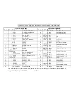
Страница 50: ...PAGE 50 Copyright Hewland Engineering Limited 2001 2008 ILLUSTRATED PARTS LIST FOR DIFFERENTIAL CONFIGURATIONS ...
Страница 64: ...PAGE 64 Copyright Hewland Engineering Limited 2001 2008 RAMP ORIENTATION Fig 37 ...
Страница 65: ...PAGE 65 Copyright Hewland Engineering Limited 2001 2009 GEARBOX TOOLING Fig 38 ...
Страница 67: ...PAGE 67 Copyright Hewland Engineering Limited 2001 2009 INSTALLATION DRAWINGS MAINCASE AND BEARING CARRIER ...
Страница 68: ...PAGE 68 Copyright Hewland Engineering Limited 2001 2008 Fig 39 ...
Страница 69: ...PAGE 69 Copyright Hewland Engineering Limited 2001 2009 Fig 40 ...
Страница 70: ...PAGE 70 Copyright Hewland Engineering Limited 2001 2008 Fig 41 ...
Страница 71: ...PAGE 71 Copyright Hewland Engineering Limited 2001 2009 Fig 42a OUTPUT FLANGE VARIATIONS ...
Страница 72: ...PAGE 72 Copyright Hewland Engineering Limited 2001 2008 Fig 42b OUTPUT FLANGE VARIATIONS ...
Страница 73: ...PAGE 73 Copyright Hewland Engineering Limited 2001 2009 Fig 42c OUTPUT FLANGE VARIATIONS ...
Страница 74: ...PAGE 74 Copyright Hewland Engineering Limited 2001 2008 2nd JUNE 2005 Fig 43 ...
Страница 77: ...PAGE 77 Copyright Hewland Engineering Limited 2001 2009 James Batchelor Design Engineer Fig 44 ...
Страница 82: ...PAGE 82 Copyright Hewland Engineering Limited 2001 2008 ...
Страница 83: ...PAGE 83 Copyright Hewland Engineering Limited 2001 2009 gear b o x They a r e d i ...
Страница 84: ...PAGE 84 Copyright Hewland Engineering Limited 2001 2008 19th July 2004 ...
Страница 85: ...PAGE 85 Copyright Hewland Engineering Limited 2001 2009 25th January 2005 Fig 47 ...