


PAGE 17
© Copyright Hewland Engineering Limited 2001-2009
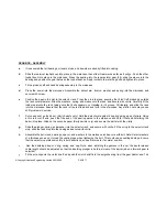
GEARBOX - ASSEMBLY
a
It is assumed that all bearings, oil seals, studs, and dowels are already fitted into casing.
b
Slide the rearmost tophat bush into place in the maincase, then slide it rearwards as far as it will go. Push the other
tophat bush into place in the maincase. Press the bearing into the reverse idler gear (39), slide the sleeve into the
bearing and position the gear between the tophat bushes. Apply loctite to the retaining bolt and tighten into place.
c
Fit the pinion shaft and head bearing assembly to the maincase.
d
Press the dowel into the maincase. Assemble the detent arm, trunion, washer and spring into the maincase and
secure with screw.
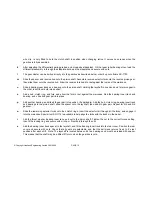
e
Position the pawl in the slot in the selector rack. Press the pin into place, ensuring that it isn’t left protruding outside
the rack outer diameter. Slide the washers, spring, and sleeve onto the rack, and secure with circlip. Carefully fit the
rubber seal onto the rack, taking care that it sits squarely, not twisted, in it’s groove. Oil liberally, and slide the rack
into the maincase. Ensure that the rack is free to slide back and forth in the maincase. Any stiction here may cause
shift problems in service.
f
Put one spacer on the barrel.
(Early barrels only).
Hold the detent arm against it’s spring using a pair of pliers. Using
a thin rod or stiff wire, push the free end of the pawl upwards in the maincase and hold it there whilst sliding the
barrel into place. Slide on the second spacer
(Early barrels only),
and secure the barrel with the circlip.
g
Slide the plunger, spring, and washer into the selector rack, and secure with circlip. Fit the oring to the selector rack
stop, slide the rack stop into the casing and secure with circlip.
h
Assemble the bell crank, bearings, spacer, and washers to the maincase, and secure with bolt. Note: Select washers
of a thickness so as not to load the casting lugs when tightening the bolt. This could cause casting damage. Ensure
that the selector operates smoothly in both directions, and self returns to it’s normal position.
i
Add the baulking plunger, o’ring, spring, and cap. Note: when installing the gearbox in the car, the baulk release
cable length should be adjusted so that the baulking plunger is held just clear of the barrel (when a forward gear is
selected).
j
Fit the wire clip onto the clutch shaft, and push the clutch shaft into the spigot bearing from the gear cluster end. The
Содержание FTR
Страница 2: ...PAGE 2 Copyright Hewland Engineering Limited 2001 2008 This page left intentionally blank ...
Страница 4: ...PAGE 4 Copyright Hewland Engineering Limited 2001 2008 This page left intentionally blank ...
Страница 27: ...PAGE 27 Copyright Hewland Engineering Limited 2001 2009 6 SPEED VARIABLE PARTS ...
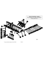
Страница 33: ...PAGE 33 Copyright Hewland Engineering Limited 2001 2009 LAYSHAFT ASSEMBLY 6 SPEED FTRE RATIOS ONLY Fig 15 ...
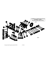
Страница 35: ...PAGE 35 Copyright Hewland Engineering Limited 2001 2009 SELECTOR ASSEMBLY 6 SPEED FTRE RATIOS ONLY Fig 17 ...
Страница 47: ...PAGE 47 Copyright Hewland Engineering Limited 2001 2009 5 SPEED VARIABLE PARTS ...
Страница 49: ...PAGE 49 Copyright Hewland Engineering Limited 2001 2009 Fig 23 BEARING CARRIER OPTIONS ...
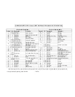
Страница 50: ...PAGE 50 Copyright Hewland Engineering Limited 2001 2008 ILLUSTRATED PARTS LIST FOR DIFFERENTIAL CONFIGURATIONS ...
Страница 64: ...PAGE 64 Copyright Hewland Engineering Limited 2001 2008 RAMP ORIENTATION Fig 37 ...
Страница 65: ...PAGE 65 Copyright Hewland Engineering Limited 2001 2009 GEARBOX TOOLING Fig 38 ...
Страница 67: ...PAGE 67 Copyright Hewland Engineering Limited 2001 2009 INSTALLATION DRAWINGS MAINCASE AND BEARING CARRIER ...
Страница 68: ...PAGE 68 Copyright Hewland Engineering Limited 2001 2008 Fig 39 ...
Страница 69: ...PAGE 69 Copyright Hewland Engineering Limited 2001 2009 Fig 40 ...
Страница 70: ...PAGE 70 Copyright Hewland Engineering Limited 2001 2008 Fig 41 ...
Страница 71: ...PAGE 71 Copyright Hewland Engineering Limited 2001 2009 Fig 42a OUTPUT FLANGE VARIATIONS ...
Страница 72: ...PAGE 72 Copyright Hewland Engineering Limited 2001 2008 Fig 42b OUTPUT FLANGE VARIATIONS ...
Страница 73: ...PAGE 73 Copyright Hewland Engineering Limited 2001 2009 Fig 42c OUTPUT FLANGE VARIATIONS ...
Страница 74: ...PAGE 74 Copyright Hewland Engineering Limited 2001 2008 2nd JUNE 2005 Fig 43 ...
Страница 77: ...PAGE 77 Copyright Hewland Engineering Limited 2001 2009 James Batchelor Design Engineer Fig 44 ...
Страница 82: ...PAGE 82 Copyright Hewland Engineering Limited 2001 2008 ...
Страница 83: ...PAGE 83 Copyright Hewland Engineering Limited 2001 2009 gear b o x They a r e d i ...
Страница 84: ...PAGE 84 Copyright Hewland Engineering Limited 2001 2008 19th July 2004 ...
Страница 85: ...PAGE 85 Copyright Hewland Engineering Limited 2001 2009 25th January 2005 Fig 47 ...