- 5 -
-
next mount cover between the collectors (8)
4.3 Fastening elements no 9, no 10, no 11.
-
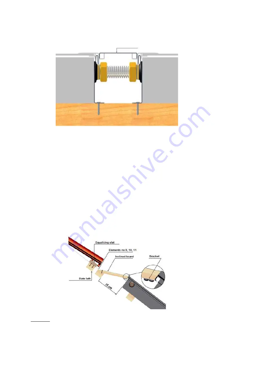
above the collectors, in the distance of 15cm (given on the cross-section D-D), build up additional lath
used for supporting upper part of the flashing,
-
delivered inclined board should be leaning on the frame in the middle part of the collector, so that the
catch of cantilever can be put in under the frame and after boring holes, fasten using two screws to addi-
tional slate lath,
-
put the corner (9) so that it overlaps previously placed side element (4), upper part of collector `s frame
and leans on the fastened inclined board,
-
on the left side fasten the corner to slate laths using graspers for flashing and screws,
-
after putting on the sealing up substance in a place of upper elements` overlay of flashing and proper
placing the element (10) we should perforating holes
3,5mm and then using screws with rubber gas-
kets fasten to the inclined board
-
analogically mount the element (11)
-
to the upper elements of the flashing screw on a slat which levels placing of declining to the flashing
slates, height of the slat “h” should be chosen accordingly to thickness of the slate
WARNING
While placing slate around the flashing it should be properly cut and well-fitted.
Element no 8
cross-section "C-C"
cross-section "D-D"


