


2
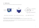
1.2 LiDAR Structure
40 pairs of laser emitters and receivers are attached to a motor that rotates horizontally.
Figure 1.2 Partial Cross-Sectional Diagram
Figure 1.3 Coordinate System (Isometric View)
Figure 1.4 Rotation Direction (Top View)
The LiDAR’s coordinate system is shown above. The Z-axis is the axis of rotation.
The origin is shown as a red dot in Figure 1.6 on the next page. After geometric transforms, all the measurements are relative to the origin.
Each laser channel has an intrinsic horizontal angle offset. When Channel 12 passes the zero degree position (y-axis) illustrated in Figure 1.4, the azimuth
data in the corresponding UDP data block will be 0°.
Содержание Pandar40
Страница 1: ......
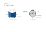
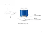
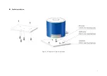
Страница 9: ...5 2 Setup 2 1 Mechanical Installation Figure 2 1 Isometric View Figure 2 2 Bottom View ...
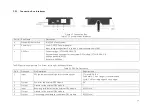
Страница 10: ...6 Quick Installation Figure 2 3 Diagram of Quick Installation ...
Страница 11: ...7 Stable Installation Figure 2 4 Diagram of Stable Installation ...
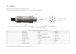
Страница 15: ...11 2 3 2 Connection Figure 2 7 LiDAR Connection When Using the Connecting Box ...
Страница 46: ......