


10
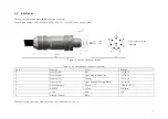
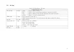
2.3.1 Connection Box Interfaces
Figure 2.7 Connection Box
Table 2.2 Connection Box Interfaces
Port # Port Name
Description
a
Standard Ethernet Port
RJ45, 100 Mbps Ethernet
b
Power Port
Use DC-005 DC power adapter
Input voltage ranges from 9 V to 48 V. Power consumption is 18 W
c
GPS Port
Connector type: JST SM06B-SRSS-TB
Recommended connector for the external GPS module: JST SHR-06V-S-B
Voltage standard: RS232
Baud rate: 9600 bps
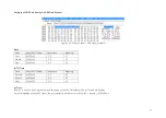
The GPS port pin numbers are 1 to 6 from left to right, defined as follows:
Table 2.3 GPS Pin Description
Pin #
Direction
Pin Description
Requirements
1
Input
PPS (pulse-per-second) signal for synchronization
TTL level 3.3 V/5 V
Pulse width: 1 ms or longer is recommended
Cycle: 1 s (from rising edge to rising edge)
2
Output
Power for the external GPS module
5 V
3
Output
Ground for the external GPS module
-
4
Input
Receiving serial data from the external GPS module
RS232 level
5
Output
Ground for the external GPS module
-
6
Output
Transmitting serial data to the external GPS module
RS232 level
Содержание Pandar40
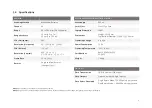
Страница 1: ......
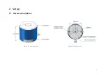
Страница 9: ...5 2 Setup 2 1 Mechanical Installation Figure 2 1 Isometric View Figure 2 2 Bottom View ...
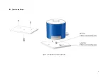
Страница 10: ...6 Quick Installation Figure 2 3 Diagram of Quick Installation ...
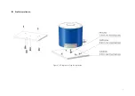
Страница 11: ...7 Stable Installation Figure 2 4 Diagram of Stable Installation ...
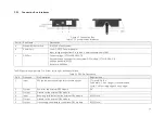
Страница 15: ...11 2 3 2 Connection Figure 2 7 LiDAR Connection When Using the Connecting Box ...
Страница 46: ......