background image

5

Installation

Read the instructions in the furnace installation manual carefully before attempting installation
or operation of the humidifier. Failure to follow these instructions may result in improper
installation and therefore, void the manufacturer’s warranty.

WARNING

Improper electrical wiring can cause personal injury, death, or
property damage. Local codes require that the unit be installed
by a properly qualified HVAC technician or electrician.

Some furnaces provide 120VAC auxiliary terminals that may be used to power the humidifier.
Since these auxiliary terminals are interlocked with the fan, no separate fan interlock relay is
required in the humidistat circuit  depending on the furnace model. These terminals are
marked HTG.Acc/Neutrals. Acc/Neutral or Hum-H/Hum-N.

When connected to these furnaces using 120VAC auxiliary terminals interlocked to the furnace
fan, connect the primary of the supplied 120/24VAC transformer to the auxiliary terminals on
the furnace. Connect the secondary of the transformer to the unit pigtails and SPST humidistat
provided. The humidifier will then turn on whenever the furnace fan is running and there is a
call for humidity. 

For systems without 120VAC or 24VAC auxiliary terminals, systems with multi-speed blowers or
non-120VAC systems, the switch contacts of a separate SPST-NO fan interlock relay is required
to be wired in series with the humidistat switch. Depending on the installation and furnace
manufacturer the coil for this relay could be:

• Wired in parallel with the coil of the NO fan relay, typically 24VAC.
• Wired in parallel with the common and heating speed tap of the units blower typically

120VAC or 240VAC.

• An inductively coupled current sensing relay on the common of the units blower.

See installation instructions on the provided 
mounting template

Содержание G-200/300

Страница 1: ...t Bypass Humidifier Installation Operation Maintenance CAUTION READ INSTALLATION OPERATION AND MAINTENANCE INSTRUCTIONS CAREFULLY FOR SAFE OPERATION EXERCISE EXTREME CAUTION WHEN WORKING WITH ELECTRIC...

Страница 2: ...tents Introduction 1 Specifications 2 Capacity Selection Guide 3 Operation 3 Installation 5 Mounting Locations 6 Maintenance 7 Troubleshooting 9 Description of Parts 11 Unit Diagram and Parts List 12...

Страница 3: ...at 71 to 72 F without controlled humidity Since every degree of temperature setback represents about 3 of your heating costs this can possibly represent a significant annual savings During the heatin...

Страница 4: ...idifier as part of the summer shut down Be sure to install a new evaporator pad at the beginning of the heating season before starting the humidifier Like your heating system and air conditioning unit...

Страница 5: ...water by using the saddle valve It is designed to be either fully open or closed A pad in the distribution tray distributes water evenly between the openings The distribution tray should be inspected...

Страница 6: ...ols and humidistat for the desired conditions 30 40 Relative Humidity is typically recommended but it is important to reduce the setting whenever extreme low outdoor temperatures occur in order to avo...

Страница 7: ...urnaces using 120VAC auxiliary terminals interlocked to the furnace fan connect the primary of the supplied 120 24VAC transformer to the auxiliary terminals on the furnace Connect the secondary of the...

Страница 8: ...recommended that when the unit is installed in this location it is supplied with hot water service 2 If the furnace has an air conditioning coil be sure the unit does not interfere with coil ends 3 R...

Страница 9: ...d be installed upstream of the conical mesh filter to reduce the frequency of cleaning Water softeners can be used to improve the quality of the supply water however deionized water is corrosive and c...

Страница 10: ...drain connection Remove the old evaporator pad and discard 5 Inspect the interior of the humidifier and remove any mineral deposits and accumulation from the frame assembly and drain tray 6 Remove th...

Страница 11: ...ould be an improper electrical installation The humidifier is designed to be used in conjunction with the furnace blower Q Water is constantly flowing out the humidifier drain and I am afraid that it...

Страница 12: ...Corrective Action Replace the evaporator pad Clean or replace conical mesh filter and fluid restrictor Increase the humidity setting on the humidistat Turn the saddle valve handle in a counterclockwi...

Страница 13: ...vaporator Pad Allows water to evaporate as warm dry air is drawn through it Must be replaced on a regular basis to maintain efficiency Fluid Restrictor Located within the water tubing of the humidifie...

Страница 14: ...001 454278 002 G 109 G 125 12 353226 002 G 206 6 G 217 12 G 123 454281 002 454280 002 G 139 454279 002 G 105 IN 2ST 352680 004 351454 015 454278 002 G 109 G 125 12 353226 002 G 206 6 G 217 12 G 123 4...

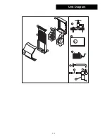
Страница 15: ...13 Unit Diagram 1 2 3 4 5 6 8 9 10 12 14 13 11 7...

Страница 16: ...edders com Humidifiers which have been installed or become part of real estate cannot be returned CareCo will receive freight prepaid only removable parts or components of such defective humidifiers 6...

Отзывы: