Important: Always read and follow the operating instructions.
• 9
Installation Instructions
Proper unit installation is necessary for safe
use and efficient operation. Proper installa-
tion also helps protect the unit from dam-
age and makes service easier. Always place
safety poster and instructions near the unit.
Location
Select a location that provides the operator with
enough space to use the equipment in a safe manner.
The area selected should be well lit, easy to clean and
should be away from oil, grease, brake lathe chips, etc.
Avoid areas where bystanders and customers may be
present.
Floor Mounting
The machine should be securely bolted to the floor
with suitable anchors using the hole at each corner of
the machine base.
Assembly Instructions
Please inspect this unit for damage/missing parts
prior to use.
Carton Contents (boxes marked 1 through 3):
Contains the base, tower and table top for your RC-
50M Manual tire changer. Be sure to check all contents
prior to assembly.
(Optional) Carton Contents (box marked 4):
Contains the Bead Loosener. Be sure to check all con-
tents prior to assembly.
Base Assembly:
Enclosed with base unit you will
find 4 (four) anchor bolts (1/2” X 3”) choose the loca-
tion for the base at this time being sure to position the
RC-50M in a clear working area. (It is suggested that
the unit is firmly mounted to the floor prior to attaching
the tower or table top.) Attach the tool tray to the base
with supplied hardware.
Tower Assembly:
Using the supplied hardware 4
(four) (12mm X 55mm hex bolts) that attaches the
tower to the base of the RC-50M, position the tower in
place. Attach the swing arm to the tower, (at this time
it is suggested that grease be added to the pivot shaft.)
The slider may be put into place at this time, (add the
return spring prior to placing the slider in the swing-
arm guide) once placed attach the bead head. Check
travel, clearances and locking mechanism prior to use.
Table Top Installation:
Prior to installation BE SURE
TO PLACE THE TABLE TOP WITH THE LOCKING KNOB
FACING FORWARD FOR ACCESS WHEN RC-50M IS
IN USE. Once the table top has been positioned check
all clearances for complete 360-degree rotation. Place
wheel jaws at desired position, making sure to place
holding pin completely through the guild hole prior to
locking the wheel in place.
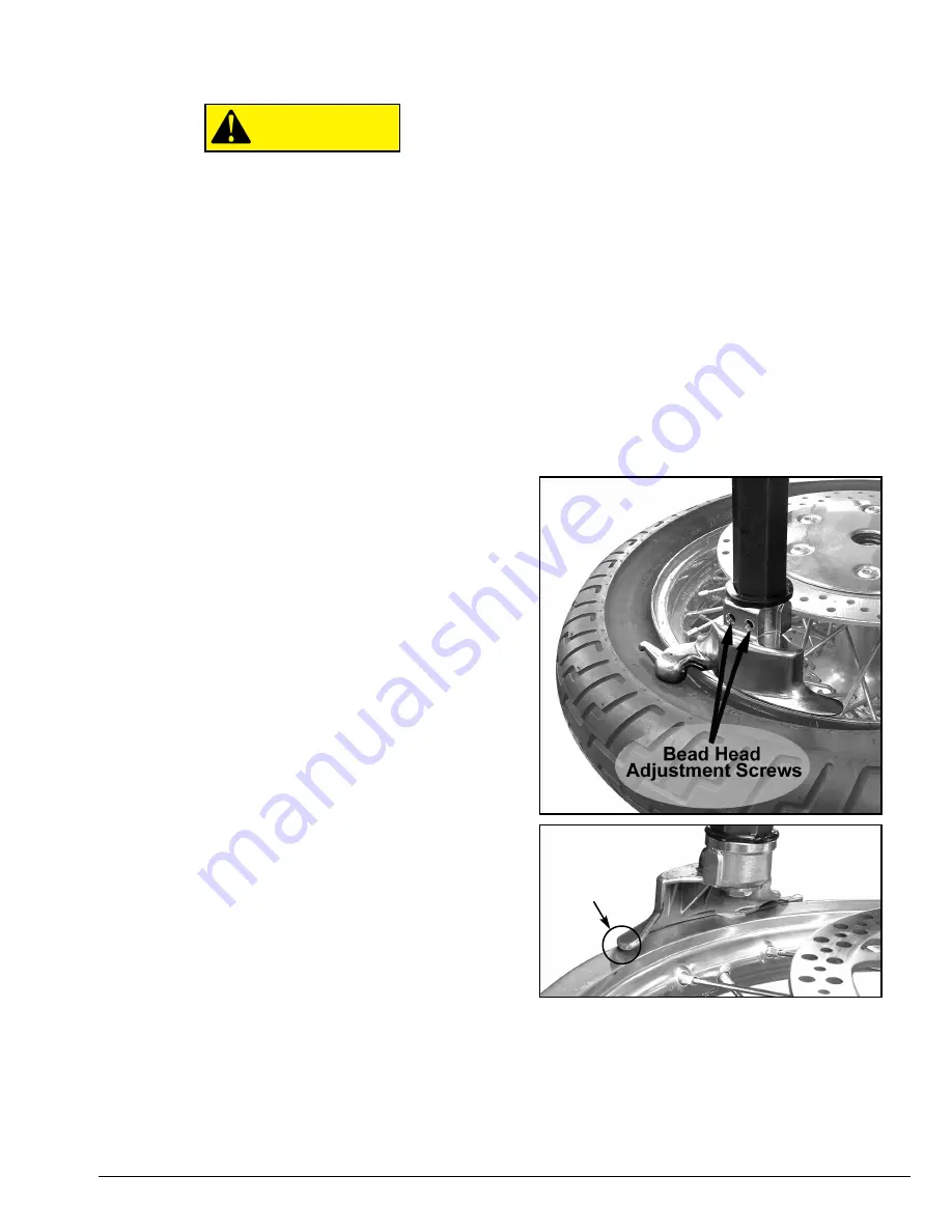
Bead-head Adjustment:
Prior to using your RC-50M
you should take a few moments to check the align-
ment of the bead-head. This is a simple procedure that
will require a 4.5mm hex wrench and an 18-inch wheel.
Set the jaws in place to accept the 18-inch wheel
(using a bare wheel will ease the adjustment process),
tighten the jaws so that the wheel is held in place.
Lower the bead head until contact is made between
the plastic rim protector and top outer edge of the
wheel. If they do not match-up, make the following
adjustment using the two adjusting screws (located
side-by-side on the bead-head mounting base, fig.1) If
needed, rotate the head until contact is made with the
wheel. The plastic protector should be touching the
wheel as close to the center as possible. The rear por-
tion of the bead head should overlap the outer edge of
the wheel so that there is approximately 1-3mm over-
hang (fig. 2.) Offset changes are made with the two
adjusting screws.
Assembly for (Optional) Bead Loosener:
Check all
contains prior to assembly. Attach support to the base
using the supplied hardware. At this point you may
now attach the link, breaker and lever arm to the sup-
port. The Bead Loosener will attach to the RC-50M by
hooking on to the locating mount.
CAUTION
Fig 1.
Fig 2.
1-3mm
overhang


