


AMMCO 800 On-The-Vehicle Brake Lathe • 21
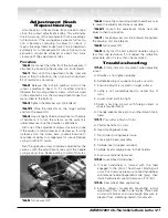
Adjustment Knob
Repositioning
At some point in the machines life you need to repo-
sition the runout adjustment knobs. This eliminates
the initial swing of the dial indicator from exceeding a
full revolution. If the swing does exceed a full revolu-
tion it becomes confusing to adjust for runout. It
means the adjustment knobs have to be turned down
extremely far to compensate for runout. Runout com-
pensation should be achieved at about four turns
clockwise of the adjustment knobs.
Procedure
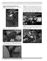
16.0
Disconnect the lathe from the hub adapter, if
attached, by loosening the drawbar star knob (black).
16.1
Start with the adjustment knobs (red and
blue) at their top position, then turn each knob down
3-1/2 revolutions clockwise.
16.2
Release the lock pin (yellow) and roll the
runout adjustment head to it’s inverted position.
Observe the two adjustment screws, which are used
in the same fashion as the two adjustment knobs that
were rolled to the bottom.
16.3
Tighten the drawbar star knob (black).
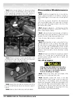
16.31
Place the indicator on the target surface
and turn the power ON.
16.4
Use a large flat blade screwdriver with plenty
of handle on it to turn the screws, as the system is
under pressure once the drawbar is tightened.
Turn one of the adjustment screws clockwise to see
if the value of swing increases or decreases. If swing
increases turn the screw back counterclockwise to
maximize it’s ability to compensate for runout. Reduce
swing to within 10 marks.
Turn the opposite screw. Alternate adjustments the
same as with the adjustment knobs until the needle
swing is very close. Reduce swing to within 10 marks.
16.5
Turn power OFF.
16.6
Rotate the runout adjustment head back over
to make the adjustment knobs accessible.
16.61
Loosen the adjustment knobs (red and
blue) to their top position.
16.7
Loosen drawbar star knob (black). Re-tighten
the drawbar star knob (black).
16.8
Turn power ON.
16.9
Verify that the dial indicator needle swing is
less than one revolution. If not, repeat the calibration
procedure until it is less than one revolution.
Troubleshooting
17.0.
Erratic indicator movement when adjusting
runout.
A. Drawbar is not tighten properly.
B. Spindle bearing or suspension parts are worn.
C. Ensure indicator is located on target surface.
D. Lathe is not counterbalanced to center line of
rotor.
E. Lower stand pivot too tight.
F. Stand is making contact with foreign object or
wheels maybe locked.
G. Change adapter drive pin to another drive hole in
head.
17.1
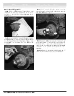
Poor surface finish of rotor.
A. Chatter band not on rotor.
B. Head Locking-lever loose.
C. Tool Holder Locking-levers loose.
D. Loose gib in head assembly.
E. Carbide insert chipped or dulled.
F. Carbide inserts maybe loose in their holders.
G. Excessive material removed.
17.2
Locked Feed Handwheel.
A. If feed handwheel is rotated with the feed
engaged to the limit of head travel, binding will
occur. Put clockwise pressure on feed handwheel
and release feed engagement knob (gray), then
rotate handwheel counterclockwise off of limit.
17.3.
Rear wheel drive applications.
A. Erratic indicator movement preventing runout
adjustment. This is due to axle in-play. Place hand
on stand member and use enough pressure to
prevent float, stabilizing indicator movement.
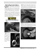
On-The-Vehicle