


AMMCO 800 On-The-Vehicle Brake Lathe • 15
Adjusting the Lathe Runout
10.0
At this point, the 800 brake lathe is ready to
be turned on and adjusted for runout. Start this
process by inserting the power cord into the twist-lock
receptacle located on the end of the control box.
10.1
Make sure lock pin (yellow) is locked into the
runout adjustment head before activating the power
switch.
10.2
Turn the power switch ON.
10.3
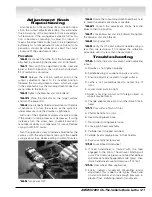
Correct for lathe runout by using the two
adjustment knobs (red and blue) located on the runout
adjustment head. First turn the red knob, then the
blue knob decreasing dial indicator movement as
much as possible until the indicator movement
improves. Continue to turn red and blue knobs alter-
nately to decrease dial indicator movement.
When
movement of dial indicator has been reduced to
.004-inch or less, adjustment is complete. Note
that resulting cut will be within .002-inch.
On-The-Vehicle
Runout Diagram
LATHE
1/2 Indicator Distance
Indicator Distance
Origin of
Movement
.002-inch
movement at
carbide inserts
.004-inch
movement
at indicator
Note that the Dial Indicator
Reads .001 (1/1000) of an
Inch Between the Marks