background image

31 


5.3 

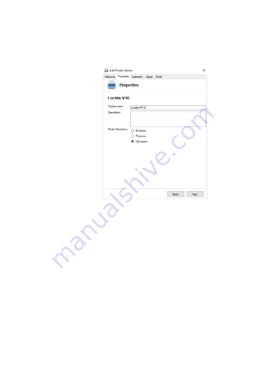
  Adding a Printer to the Loctite Operator Station PC Software 


Before creating a print job, the new printer needs to be added to the software. 
To do this follow the below instructions: 


1.


Open Loctite Operator Station Software 

2.


Select 

Tools 

Managers

 > 

Printer Manager

 > 

Add 


3.


Follow the instructions on the 

Printer Connection Wizard. 

 Set the printer resolution to 

100 micron

.


4.


Select ‘

next’

 and follow the calibration instructions in section 6 


Содержание Loctite EQ PR10.1 DLP

Страница 1: ...Loctite EQ PR10 1 DLP 3D Printer Operating Manual IDH 2416987 ...

Страница 2: ... 4 5 Asssembling the Build Platform 12 4 6 Assembling the Basins 13 4 7 Installing the Safety Basin 14 4 8 Installing the Resin Basin 16 4 9 Run the Diagnostics Check 17 4 10 Positioning the Build Platform 19 4 11 Alligning the Build Platform 20 5 Loctite Operator Station PC Software 23 5 1 Installing the Software 23 5 2 Main Screen 24 5 3 Adding a Printer 31 6 Calibration 32 6 1 Create a Calibrat...

Страница 3: ...3 7 6 Cleaning the Basin 36 7 7 Removing a Failed Print 37 8 Troubleshooting 38 9 Care and Maintenance 39 10 Spare Parts and Accessories 39 11 Warranty 40 ...

Страница 4: ...s recommendations for better handling or adjustment of the unit during operation as well as for service activities 1 2 Items Supplied 1 EQ PR10 1 DLP 3D Printer 1 Base Frame or Cabinet 1 Safety Basin 1 Starter kit Including 1 Spatula 1 Resin Puller 1 Resin Curing Flash Light 1 Resin Basin 1 Build Platform 1 Nitrile Gloves 1 Spray bottle 1 Funnel with filter 1 Operating Manual 1 PC Software on USB ...

Страница 5: ... only by authorized service personal Avoid contact with chemicals and wear protective clothing gloves and goggles Do not look directly at Projector UV light or at projector UV light reflected by a reflective surface Doing so could cause eye damage Always wear UV blocking eye protection when operating this machine Never operate this product any way other than described in this manual Doing so risks...

Страница 6: ...xchangeable basin glass bottom coated with ultra high chemical resistance PTFE 3 Description 3 1 Theory of Operation The operator loads resin into the resin basin and selects a print job which has been prepared on the supplied printer PC software The software requires a Windows 10 operating system The build platform then lowers into the resin and the projector projects an image of the part layer b...

Страница 7: ... Cover UV blocking 2 Build Platform 3 Resin Basin 4 Touch Screen 5 On Off Switch located on the underside of the touch screen 6 DLP Projector Housing 7 Storage Cabinet 8 USB Connection located on the right hand side of the touch screen 1 2 3 4 5 6 7 8 ...

Страница 8: ...8 3 3 Machine Connections 21 Power Connector 22 Ethernet Connector 21 22 ...

Страница 9: ... on the home screen This menu allows you to access other screens which contain the following information ABOUT Firmware for both the printer and the touchscreen Print Information including number of items printed and total number of layers Network information including Hostname and LAN information CONTROLS Manually move the build platform up and down Manually turn the projector on and off TESTS Ru...

Страница 10: ...rive and the corresponding approximate print times and the volume of resin required to print Print jobs are selected by pressing the tick on the right hand side and then pressing the Add button Several print jobs can be copied at once on the printer Menu Group Home Screen Print Job Selected Once a print job has been added it will display on the home screen You can preview a 3D model of the print b...

Страница 11: ...11 The job can be deleted by swiping left on the Planned Jobs screen To begin printing press the Start button ...

Страница 12: ...djusting the feet on the printer Ensure the base is bolted to the ground that the printer is bolted to the base 4 3 Connecting the Power Cord Connect one of the supplied power cords to the appropriate supply and connector 21 4 4 Remove the Projector Protective Cap The projector is shipped with the projector cap in place This must be removed before use It is possible to remove the cap by reaching i...

Страница 13: ...me of the basin Position the holes in the tilt blocks towards the back of the basin The basins are identifiable by the color of the anodization The clear anodization indicates it is a resin basin and has a PTFE coating The black anodization indicates it is a safety basin with no PTFE Coating DO NOT INTERCHANGE THE BASINS Do not drop the box containing the basin Do not drop the basin Never touch th...

Страница 14: ...ews holding it in place 2 Remove the front panel of the printer housing This is magnetically held in place 3 Carefully pick up the safety basin white silicone holding it gently by the frame 4 Slide the safety basin into position above the projector with the tilt blocks facing the rear of the printer ...

Страница 15: ...ion Ensure the rings are on the outside It is important the pins are inserted with the rings on the outside as shown below Failure to do so could result in the inability to remove the pins 6 Replace the front panel 7 Re attach the base plate and secure into position with screws ...

Страница 16: ...n above the projection hole with the tilt blocks positioned towards the rear of the printer 5 Tilt the basin downwards at the front and move into position under the stopping blocks 6 Lower the basin so it is horizontal and resting in position 7 Align the holes on the tilt blocks with the holes in the frame 8 Insert the pins to hold the basin in place Ensure the rings on the pins are on the outside...

Страница 17: ...jector and z axis motor Ensure a USB flash drive is connected prior to running the diagnostic checks To carry out the diagnostics check 1 Power on the printer using the on off switch located on the underside of the touchscreen 2 Wait for the printer to boot up 3 Open the settings menu from the home screen by pressing the gear button 4 Select Tests ...

Страница 18: ...firm each action 7 The diagnostic checks finish with a test print During the test print the Z axis carriage lowers to the basin and gradually travels upwards while the projector flashes the Loctite logo 8 Once this has completed press Done to finish Always wear UV blocking safety glasses when the projector is on ...

Страница 19: ...m 1 Move the z axis carriage to the top position this is done by entering the Controls screen from the settings menu and pressing the platform Up button 2 Set the build platform so that the groove is matching the receiving slot 3 Ensure it is facing the correct direction and push into position 4 Screw the manual top screw down and tighten into position ...

Страница 20: ...f the print tray that follows 4 11 Aligning the Build Platform To produce accurate prints the build platform needs to be aligned with the basin To align the build platform 1 Ensure that the build platform and basin are clean 2 Move the build platform the top position this is done by entering the Controls screen from the settings menu 3 Loosen the 4 screws holding the ball joint so the build platfo...

Страница 21: ... the build platform so that it lies flat and is squarely aligned with the basin Hold the build platform with light gentle pressure inside the basin and tighten the set screw on the front of the build platform to fix the vertical movement of the build platform Be careful not to apply much pressure as this will cause Z axis misalignment 7 Finally tighten the small Allen screws evenly around the ball...

Страница 22: ...22 A tray must be paired to the build platform that it will be used with This is a procedure that must completed each time a new tray or build platform is used ...

Страница 23: ... system 1 Insert the supplied USB flash drive into your computer 2 Navigate to the USB flash drive 3 Open Setup exe 4 Follow the on screen instructions on the installation wizard 5 You will be prompted to request a license activation key to complete the installation To do this copy the text in the box and email it to activate lic loctite pr10 com 6 You will receive an email reply which will contai...

Страница 24: ...fter opening the Loctite Operator Station PC software the following screen will be displayed 1 Action bar 2 Menu bar 3 Work area 4 Property panels 5 Total number of models 6 XYZ orientation 5 2 1 Action Bar Use the action bar to perform actions in the work area Below is an explanation of all the icons and their application 1 2 3 4 6 5 ...

Страница 25: ... up box Rotate Item shortcut R In this mode click the left mouse button to select a model in the work area for rotating it in the X and Y and Z directions You can also enter a value for rotation in the pop up box Change Camera View In this mode click the left mouse button and move the mouse to change the camera view of the model Add Manual Support In this mode click the left mouse button and move ...

Страница 26: ...on model to the work area 5 2 2 4 Tools Menu When opening the Tools menu the below options are shown Material Manager Open the Material Manager Printer Manager Open the Printer Manager 5 2 2 5 View Menu When opening the View menu the below options are shown View Ports Annotations When selected different viewpoints can be chosen Model View the model as a solid Wireframe View the model as a wire fra...

Страница 27: ...or the following functions Align models on the build platform Clone models Add modify or remove support cones 5 2 4 Property Panels There are four property panels Print job navigation Print Job properties Model properties Support properties These are loated on the right hand side of the home page and are accessed by clicking on them The following sections describe the panels and their function 5 2...

Страница 28: ...e available materials Name The print job name that will be displayed on the printer Manufacturer Select the manufacturer of the resin that will be used for the print job Product Select the resin product that will be used for the print job Initial Layers Number of initial layers The intial layers are used to bond the print job to the build platform Layer Thickness The layer thickness mm Rehab Time ...

Страница 29: ...face between 175 and 185 degrees Orange Small angled surface between 150 and 210 degrees White When placing a grid support a surface can turn white The white overlay shows the area that will be filled with support cones All Axis Locked When True the model will be scaled by the same factor in all axis Factor The scaling factor Cone Distance The distance between the grid support cones mm Cross Suppo...

Страница 30: ...ttom Height Height of the bottom cone structure Bottom Radius Radius of the bottom of the cone structure Middle Radius Radius of the middle of the cone structure Top Height Height of the top of the cone structure Top Radius Radius of the top of the cone structure Total Height Total height of the support cone Colour Grey Non selected support cone s Selected Highlighted single support cone Selected ...

Страница 31: ...to be added to the software To do this follow the below instructions 1 Open Loctite Operator Station Software 2 Select Tools Managers Printer Manager Add 3 Follow the instructions on the Printer Connection Wizard Set the printer resolution to 100 micron 4 Select next and follow the calibration instructions in section 6 ...

Страница 32: ...e Leave the calibration window on the software open 6 2 Printing a Calibration Print Once the print job has been saved onto a USB flash drive it is ready for printing Before printing ensure the printer is prepared See section 7 2 Preparation Before Printing 1 Insert the USB flash drive into the printer 2 Select the print job from the Add a Print Menu on the touchscreen 3 Ensure there is enough res...

Страница 33: ...r is wearing the correct PPE 1 Record the 4 measurements between the blocks 2 Enter these measurements in the software 3 Select back to regenerate the calibration print using the new values Repeat the previous steps Carry out this procedure 3 times to fully calibrate the printer Or once the measured values are 160 0 2mm and 80 0 2mm Ensure the previous build is removed from the build platform befo...

Страница 34: ...ash drive 7 2 Preparation before Printing Before printing the following checks should be made 1 Ensure the basin and build platform have been installed and aligned correctly 2 Ensure the printer has been calibrated 3 Check the basin is not damaged and that it is clean 4 Check the build platform is not damaged and that it is clean 7 3 Printing 1 Insert the USB flash drive to the printer 2 Select th...

Страница 35: ...Build 1 Ensure the build platform is in the up position 2 Allow the excess resin to drip into the basin 3 Unscrew the black knob and slide the build platform out 4 Wipe the build platform carefully with a paper towel so the excess resin does not drop on the printer 5 Place the build platform on a flat surface 6 Use the included sharp metal scraper to slide under the model and remove it from the bu...

Страница 36: ...m to remove any remaining resin Always wear gloves and safety glasses when handling resin or IPA 7 6 Cleaning the Basin 1 Remove the two pins holding the resin basin to the frame of the printer 2 Carefully remove the resin basin keeping it as level as possible while doing so 3 Pour the resin back into the container using a funnel Use a filter to remove any contamination 4 Spray the resin basin wit...

Страница 37: ...ler on the liquid resin Make sure the resin puller is in contact with both the liquid and the cured resin 7 Place the UV flashlight below the resin puller and shine upwards for 20 seconds Do not look directly at the UV light doing so could damage your eyes Always use UV blocking safety glasses 8 Carefully pull on the resin puller until the cured resin releases from the basin 9 Remove the resin fro...

Страница 38: ...properly aligned It is recommended to use fresh resin if reusing resin ensure it is filtered Make sure the correct material is selected and check the settings When preparing the print job on the software ensure it is located on the platform bed Print job slicing are sometimes generated with defects coming from the file Do a scroll through check of the slices paying attention that the image is comp...

Страница 39: ...unctionality of all components of the printer Monthly Inspect the build platform for any damage such as marks or scratches Inspect the resin basin for any damage such as marks or scratches 10 Spare Parts and Accessories Description Item No Starter kit Including Spatula Resin Puller Resin Curing Flash Light Resin Basin Build Platform Nitrile Gloves Spray bottle Funnel with filter 2312295 Build Plat...

Страница 40: ...40 ...

Страница 41: ...ding where products parts or attachments for use in connection with the Products are available from Henkel the use of products parts or attachments which are not manufactured by Henkel no claim shall be allowed No Products shall be returned to Henkel for any reason without prior written approval from Henkel Products shall be returned freight prepaid in accordance with instructions from Henkel NO W...

Страница 42: ...centre SINGAPORE 149598 Henkel China Company Ltd No 928 Zhang Heng Road Zhangjiang Hi Tech Park Pudong Shanghai China 201203 Henkel Loctite Korea 8F Mapo Tower 418 Mapo dong Mapo gu Seoul 121 734 KOREA Henkel Japan Ltd 27 7 Shin Isogo cho Isogo ku Yokohama 235 0017 JAPAN Henkel AG Co KGaA Standort München Gutenbergstraße 3 85748 Garching b München Deutchland www equipment loctite com and designate...

Отзывы: