background image

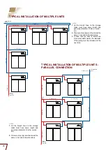
20mm (3/4”)

15mm (1/2”)

20mm (3/4”)

25mm (1”)

25mm (1”)

(3/4”)

(3/4”)

25

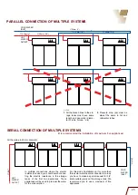
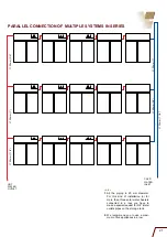
PARALLEL CONNECTION OF MULTIPLE SYSTEMS

notes

1.  

All the branch lines to the sto

-

rage  tanks  must  have  same 

length  and  geometry  (diame

-

ter of tube, curves… etc)


2.  

Pressure  drop  (¢p)  must  be 

almost  the  same  in  hot  and 

cold-water tubes

COLD WATER 

INLeT

HOT 

WATER 

OUTLET

SERIAL CONNECTION OF MULTIPLE SYSTEMS

(It is recommended the installation of maximum five appliances)

In  multiple  connections  where  the  electric 

resistance is used, you should avoid connec

-

ting  the  electric  resistance  in  the  storage 

tanks  of  the  first  two  appliances.  These 

appliances will be used to pre-heat the water 

for the consumption. 

For this kind of installation (or for more than 

three solar water heaters connected in a row) 

you have to make a special request for 3/4” 

inlets-outlets pipes on the storage tank. We 

recommend  you  to  use  a  maximum  of  five 

appliances.

All the piping in 20 mm diameter.

COLD 

WATER 

INLeT

HOT 

WATER 

OUTLET

Содержание NovaSun 200

Страница 1: ...TECHNICAL MANUAL INSTALLATION MAINTENANCE AND USE INSTRUCTIONS ENGLISH ...

Страница 2: ...limatic conditions and for all types of water qualities A philosophy that leads the way and makes us as professionals feel the weight of responsibility and obligation to offer products and services that are in harmony with the environment and man To hand over a better world to our children Always true to our principle for excellence in design and continuous advance ments HELIOAKMI today offers hig...

Страница 3: ...AGE TANK AND COLLECTOR ON THE SUPPORT BASE Page 14 CONNECTION INSTRUCTIONS OF THE STORAGE TANK COLLECTOR AND COMPONENTS Page 16 FILLING INSTRUCTIONS OF THE CLOSED CIRCUIT WITH THERMAL FLUID Page 18 DESCRIPTION OF THE PARTS OF THE ELECTRIC RESISTANCE AND THERMOSTAT CONNECTION INSTRUCTIONS Page 20 SPECIAL CLIMATIC CONDITIONS Page 22 INSTRUCTIONS AFTER THE INSTALLATION Page 24 TROUBLESHOOTING REPLACE...

Страница 4: ...s material low carbon steel 1 5 mm Cylinder s internal Protection durosmalt 80 120 microns Additional protection magnesium rod Electric resistance copper Thermostat bipolar of four contacts Power rate available from 0 8kW 4kW TECHNICAL SPECIFICATIONS OF THE STORAGE TANK EXTERNAL DIMENSIONS ALL MODELS Collector with titanium selective treat ment TECHNICAL SPECIFICATIONS OF THE COLLECTOR 1 External ...

Страница 5: ... on the outside The collector is packed with 4 plastic protective elbows atta ched on each corner which are fast tightened around the collector with a plastic strap upon special order the collectors could be delivered in groups of 10 pcs on a wooden pallete All the parts of the support base the plastic bag with the connection fittings the thermal fluid and other accessories are packed in a carton ...

Страница 6: ...ater which will fulfil your needs For a better choice of the appliance the local climate conditions must be taken into a serious consideration as well as your needs for hot water The energy saving that you will have with the NOVASUN solar water heater depends on the use of hot water the use of the electric resistance and the local weather conditions Under fa vou rable weather conditions the energy...

Страница 7: ...t equipment must be used The installer has to choose propose and install this different equipment always under the concurrent opinion of the customer For installation on a sloping roof the D plates must be screwed with the appro priate screws and nuts on the roof tim ber in order to secure the right and safe installation of the solar water heater In regions subject to heavy snowfalls it is very im...

Страница 8: ...8 A U U D D C E Z Z B B F F C Support base for 200 260 300 with 2 collectors Assembly diagram of the support base on a flat surface ...

Страница 9: ...by any obstacle trees buildings etc see obstacle diagram page 10 The same support base is used for either sloping or flat sur faces Connect the plates A B C D U and Z by screwing them tight as shown in the drawings For models 260 and 300 screw also the plates F Screw gently the bottom plate E on the plates B attention The top plate E is adjusted after the placement of the collectors Plumb the supp...

Страница 10: ...its installation on a tiled rood two additional plates E 840mm length are required These additional plates replace the plates C 1150mm length Alternatively for the formation of the parallelogram frame you can use the existing plates E 840mm length in the place of the plates C The plates C 1150mm by making two holes 10 where required will be installed in the place of the plates E 10 ...

Страница 11: ...tes B are tightly screwed on the holes of the plate A Screw gently the bottom plate E on the plates B attention The top plate E is fixed after the place ment of the collector s note The standard support base can be used also for surfaces with minimum inclination 15o and maximum 32o For smaller or greater inclinations diffe rent equipment is offered OBSTACLE TABLE Latitude Distance between collecto...

Страница 12: ... Thermal fluid outlet pipe from the collector to the storage tank 11 Collector s 12 Pipe unions collector connectors Only for models with two collectors 13 Bottom left hand collector pipe 13A Plug 1 2 14 Filling pipe for the closed circuit 14A Plug 1 2 15 Cold water inlet pipe indication cold inlet 15A Reducer 3 4 1 2 16 Thermal fluid outlet pipe from the storage tank to the collec tor Indication ...

Страница 13: ...13 01A 01B 20A 14A 17A 14 15A 15 16 17 12 19 03 07 07 18 20 18 20 17 17A 15A 15 18 03 03 ...

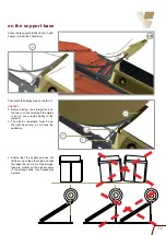
Страница 14: ...and centralize the collector s on the support base For the models 200 260 and 300 which consist of two collectors you must connect them to each other by using the pipe unions 12 supplied with each appliance Secure the bottom part of the collector s by screwing tightly the bottom plate E on the plates B Screw tightly the top plate E on the plates B securing the collector s E E Z 20A B E A 12 B Inst...

Страница 15: ... on the two U check carefully if the plates U and Z are screwed tightly to the plates B b The electric resistance must be on the right hand side as we face the appliance c Ensure that the appliance does not tilt from one or the other side and that the tubes 02 and 14 of the storage tank are vertical on the highest point of the storage tank Use necesserily a plumb Z B E U 20A U ...

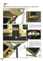
Страница 16: ...ch is located on the bot tom left hand side of the collector and use Teflon or oakum for their complete water tightness For models 200 260 and 300 which have two collectors connect them by using the collector connector pipe unions 12 supplied with each applian ce 17 17A 13A 12 Connection instructions of the storage tank collector and ...

Страница 17: ...lve type 15BC use the appropriate for each case procedure Connect the cold water supply to the spherical switch and turn the cold water supply on until the storage tank is com pletely filled When you are filling the storage tank with water the outlet of hot water 08 should be opened Connect the hot water supply to the storage tank outlet pipe 08 Indication hot outlet After connecting all the fitti...

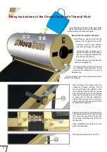
Страница 18: ...case of Helioakmi S A The use of water only or other liquid may cancel the validity of the warranty 20 Place the protective side cover 20 12 Add some more fluid in the closed circuit until it overflows from the tubes 14 and 02 Screw the plug 14A onto the tube 14 and fix the safety valve 02A onto the tube 02 Check carefully all connections for com plete water tightness 14 02A 14A 02 17A After the f...

Страница 19: ... 200E x 4 20m2 18 lt 16 lt 2 lt 14 5 lt 3 5 lt 12 5 lt 5 5 lt 12 lt 6 lt 10 5 lt 7 5 lt 9 lt 9 lt NOVASUN 260 x 4 20m2 21 lt 19 lt 2 lt 16 5 lt 4 5 lt 14 5 lt 6 5 lt 14 lt 7 lt 12 5 lt 8 5 lt 10 5lt 10 5 lt NOVASUN 300 x 4 20m2 22 lt 19 5 lt 2 5 lt 17 5 lt 4 5 lt 15 5 lt 6 5 lt 14 5 lt 7 5 lt 13 lt 9 lt 11 lt 11 lt NOVASUN 300E x 5m2 23 lt 20 5 lt 2 5 lt 18 5 lt 4 5 lt 16 lt 7 lt 15 5 lt 7 5 lt 13...

Страница 20: ...switch indication F or S CONNECTION OF THE CABLES 1 Turn off the power main supply 2 The cover of the electric resistance is on the right hand side of the storage tank Unscrew the two screws and remove the cover 3 The thermostat is adjusted from the factory at 60o C You can adjust it at the temperature you wish by using the temperature control 34 In that case we advise that the temperature you wil...

Страница 21: ...order the electric resistance can be offered with power from 800W to 4000W For power of 110V the electric resis tance is available upon special order with power from 800W to 2000W note A certified electrician must make all the electric connections Ensure that all the electric connections comply with the electric regulations applicable in your area and your buil ding Do not turn on the electric res...

Страница 22: ... be good enough for the safe installation of the appliance Special climatic conditions To assemble the support base follow the same assembly procedures mentioned on pages 9 10 and 11 12 for flat or sloping surfaces For the connection of the plates U Z and B use the long screws small step nuts Before you adjust the metal belts around the storage tank place the rubber profile between the storage tan...

Страница 23: ...port base carton For the safer installation of your applian ce we recommend you to secure the storage tank on the support base using more mettal belts than the ones illustra ted in the photos All the parts and accessories of the typhoon set are packaged in one car ton which carries on the outside the description TYPHOON SET For installation on a sloping roof we recommend you to use more metal belt...

Страница 24: ...er heater continues not to supply hot water contact your local distributor B IF THE SOLAR WATER HEATER DOESN T SUPPLY HOT WATER WITH THE ELECTRIC RESISTANCE 1 Turn off the power supply and remove the resistance s cover 2 Check the safety thermal switch F on the thermostat which has to be pushed in 3 Check the wiring between the thermo stat and the electric resistance 4 Check if the thermostat is a...

Страница 25: ... installation of maximum five appliances In multiple connections where the electric resistance is used you should avoid connec ting the electric resistance in the storage tanks of the first two appliances These appliances will be used to pre heat the water for the consumption For this kind of installation or for more than three solar water heaters connected in a row you have to make a special requ...

Страница 26: ... of tube curves etc 2 Pressure drop p must be almost the same in hot and cold water tubes TYPICAL INSTALLATION OF MULTIPLE UNITS notes 1 All the branch lines to the storage tanks must have same length and geo metry diameter of tube curves etc 2 Pressure drop p must be almost the same in hot and cold water tubes 3 In case that you have to install one more solar water heater the diameter of the pipi...

Страница 27: ...es 1 All the piping in 20 mm diameter For this kind of installation or for more than three solar water heaters connected in a row you have to make a special request for 3 4 inlets outlets pipes on the storage tank 2 We recommend you to use a maxi mum of five appliances in a row COLD WATER INLET HOT WATER OUTLET ...

Страница 28: ...ece Tel 30 210 5595 624 210 5595 625 210 5595 626 Fax 30 210 5595723 web site www helioakmi gr e mail megasun helioakmi gr NOTE HELIOAKMI S A reserves the right to change any specifications of the product and their accessories without prior notice 0709 ...

Отзывы: