background image


ASSEMBLY 

(cont)

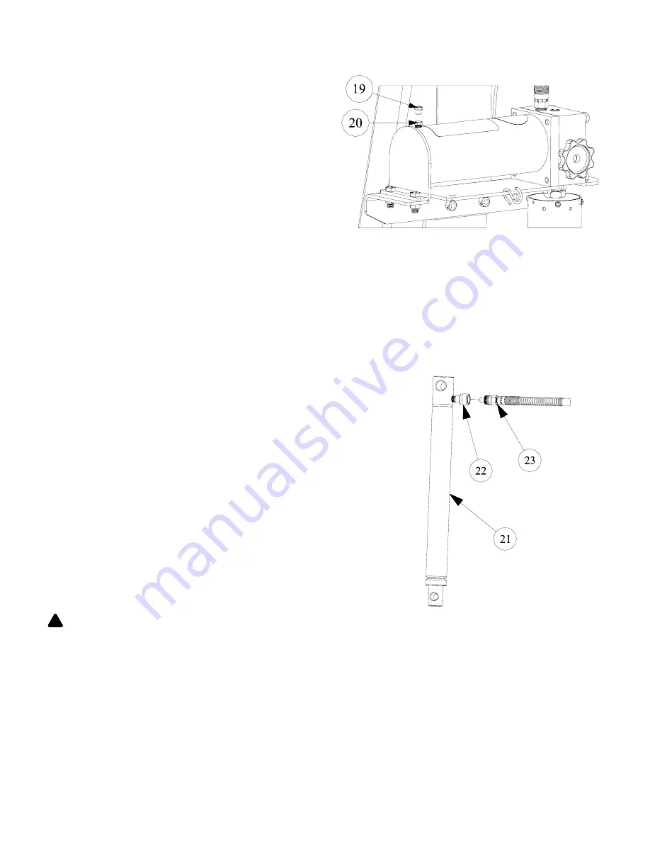
5. Remove the shipping plug [#19] from the pump [#12] 

as shown in Figure 7.

6. Check the oil level in the pump. The oil should be 1” 

to 1-1/4” from the bottom of the hole. If the oil level is 

low, add hydraulic fluid equivalent to Conoco MV22 

until the level is 1” to 1-1/4” from the bottom of the 

hole.

7. Install the breather vent plug [#20], provided with the 

crane, in the pump [#12] in the same hole the ship

-

ping plug [#19] was removed from in Step 5.

Hydraulic Cylinder Installation

Any air in the cylinder [#21] must be removed from the cylinder 

for proper functioning of the crane.

1. Remove the protective cap and seal from the quick coupler 

[#22] on the cylinder [#21]. 

2. Connect the hydraulic hose [#23] to the quick coupler [#22] on 

the cylinder [#21] by inserting the male end of the hose [#23] 

into the quick coupler [#22] and thread the quick coupler’s col

-

lar onto the hose.

3. Support the cylinder [#21] so the end with the quick coupler 

[#22] is higher than the rod end. Route the hose [#23] from 

the cylinder [#21] back to the pump so the hose [#23] is lower 

at the end that connects to the cylinder [#21] than at the end 

that connects to the pump.

4. SLOWLY extend the cylinder rod from the cylinder [#21] by 

closing the release knob and actuating the pump until the 

cylinder rod is fully extended. After the cylinder rod has been 

extended, open the release knob and hold the cylinder so that 

the quick coupler fitting is on the upper part of the cylinder and 

the cylinder rod is pointing down. Carefully push the rod into 

the cylinder until it is fully retracted. Repeat this process to 

ensure there is as little air as possible left in the cylinder. 

WARNING:


Any operation of the cylinder while detached 

from the crane must be done carefully. If the cylinder is 

extended too quickly or is pressurized to much it poses 

the possibility of hitting someone, moving unexpectedly, or 

breaking apart and may lead to property damage, serious 

personal injury, and/or death.

5. Disconnect the hydraulic hose [#23] from the quick coupler 

[#22] once all the air has been purged from the cylinder.

Figure 7 

Figure 8 


!

Содержание HW93809

Страница 1: ...bol It is used to alert you to potential personal injury hazards Obey all safety messages that follow this symbol to avoid injury or death SFA Companies 10939 N Pomona Ave Kansas City MO 64153 custome...

Страница 2: ...tes abnormally shall be removed from service until repaired If the equipment has been or is suspected to have been subjected to an abnormal load or shock immediately discontinue use until inspected by...

Страница 3: ...50 3 4 35 3 4 82 640 lbs ASSEMBLY Hydraulic Pump Installation The HW93809 is available with a hand powered pump MP 100 WARNING Use of the wrong pump model on the crane can cause the crane to be overl...

Страница 4: ...at the heads of all the bolts pass through the keyhole slots in the bracket 5 5 Once the heads of all the bolts 1 3 have passed through the keyhole slots in the bracket 5 lower the pump 4 so the bolts...

Страница 5: ...acket 11 using two 5 16 x 3 4 bolts 15 and two 5 16 lock washers 16 The 5 16 x 3 4 bolts 15 thread into tapped holes in the air pump 12 3 Attach the S hook 17 to the hole in the pump bracket 11 as sho...

Страница 6: ...her than the rod end Route the hose 23 from the cylinder 21 back to the pump so the hose 23 is lower at the end that connects to the cylinder 21 than at the end that connects to the pump 4 SLOWLY exte...

Страница 7: ...ring 27 into the groove on the retaining pin 25 as shown in Figure 10 9 Align the hole on the quick coupler end of the cylinder 21 with the holes of the cylinder mounting plates 28 lifting the boom i...

Страница 8: ...nsion pin must be in place before operating the crane and the capacity for that ex tension position must not be exceeded Operating the crane without the extension pin or with a load that exceeds capac...

Страница 9: ...raised Pay careful attention to how the load will react when raised If the center of gravity of the load is not directly under the crane s capturing device or the load is awkwardly captured the load a...

Страница 10: ...storage 1 Remove the leg positioning pin from each of the crane s legs 2 Rotate the legs outward until they clear the crane s frame 3 Separately lift each of the legs and rotate them until they are v...

Страница 11: ...o report any problems Use the following procedures to inspect the crane for wear or damage Inspect Crane Frame Chain and Hook 1 Check the crane for corrosion cracked welds or any other damage such as...

Страница 12: ...turer to repair this crane NEVER use spare parts from other sources they may not be designed to be used on this crane or rated at the same capacity TROUBLESHOOTING Symptom Possible Cause Corrective Ac...

Страница 13: ...reference of location and position in the assembly sequence When ordering parts give model number part number and parts description Call or write for current pricing Hein Werner Customer Support 10939...

Страница 14: ...ment 1 10 817 02008 Base Weldment 1 11 817 04048 Boom Pivot Pin 1 12 230 12001 Retaining Ring External 14 13 204 01707 Washer Plain 8 14 817 04030 Cylinder Rod Pin 1 15 353 40107 Crane Hydraulic Cylin...

Страница 15: ...d Grip 2 29 200 31206 Capscrew Hex Head 1 30 204 01200 Washer Flat 5 31 082 50026 Tubing Round 1 32 817 04047 Link 4400 lb 2 33 470 23023 Shaft 3 4 dia 1 34 201 01220 Capscrew Socket Head 2 35 203 012...

Страница 16: ...ATSOEVER 3 ANY IMPLIED WARRANTIES INCLUDING WITHOUT LIMITATION THE IMPLIED WARRANTIES OF MERCHANT ABILITY AND FITNESS FOR A PARTICULAR PURPOSE SHALL BE LIMITED TO TWO YEARS OTHERWISE THE REPAIR REPLAC...

Отзывы: