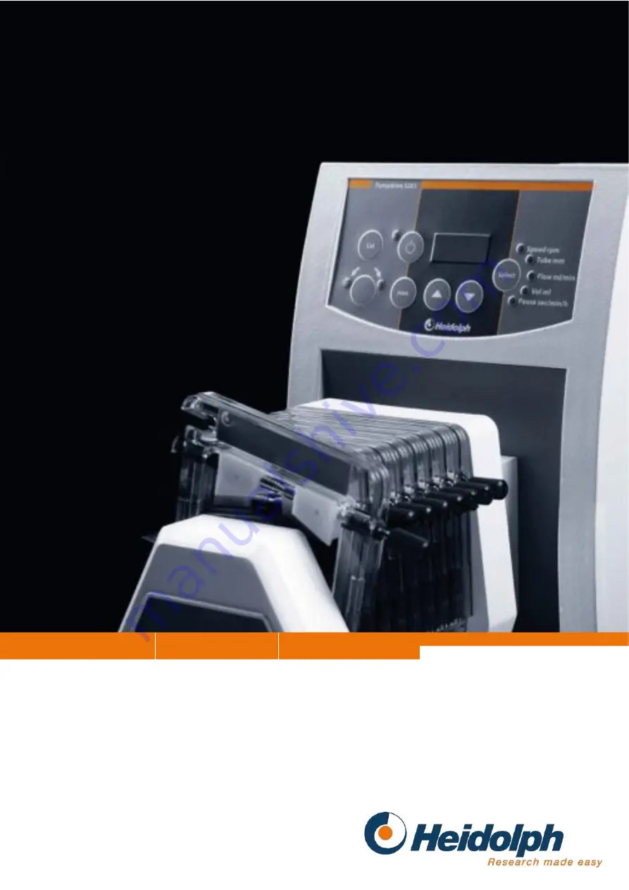
background image

Dosing and Dispensing

Precise

Leading Safety Standards

Superior Ease of Use

Reduce Cost of Ownership

Operating Instructions

Perestaltic Pumps

Operating instructions must be read before initial start-up.

Please follow the safety instructions provided.

Please keep for future reference.

Содержание PD 5001

Страница 1: ...fety Standards Superior Ease of Use Reduce Cost of Ownership Operating Instructions Perestaltic Pumps Operating instructions must be read before initial start up Please follow the safety instructions provided Please keep for future reference ...

Страница 2: ...2 IDI DEUTSCH Seite 3 41 IEI ENGLISH page 42 79 IFi FRANÇAISE page 80 117 ESi ESPAÑOL página 118 156 ITALIANO pagina 157 195 I ...

Страница 3: ...UMPENANTRIEB 13 4 2 MONTIEREN DES MEHRKANALPUMPENKOPFES AN DEN PUMPENANTRIEB 14 5 SCHLAUCH UND CASSETTE MONTIEREN 14 5 1 CASSETTE SMALL 15 5 1 1 OPTIMIEREN DER ANPRESSDRUCKEINSTELLUNGEN 16 5 1 1 1 FÜR MAXIMALE SCHLAUCHLEBENSDAUER 16 5 1 2 PUMPENBETRIEB BEI TEILWEISER BELEGUNG DES MEHRKANALPUMPENKOPFES 16 5 1 3 HERAUSNEHMEN DER SCHLAUCHCASSETTEN 17 5 1 4 VERLÄNGERUNG DER STOPPERSCHLÄUCHE 17 5 1 4 1...

Страница 4: ...SDAUER DER SCHLÄUCHE 34 13 FÖRDERMENGEN AUSWAHLTABELLE SCHLÄUCHE ZU EINKANALPUMPEN 35 14 FÖRDERMENGEN AUSWAHLTABELLE SCHLÄUCHE ZU MEHRKANALPUMPEN 36 REINIGUNG UND WARTUNG 37 ABBAU TRANSPORT UND LAGERUNG 37 ENTSORGUNG 37 STÖRUNGEN UND DEREN BESEITIGUNG 38 TECHNISCHE DATEN 39 15 PERISTALTIKPUMPENANTRIEBE 39 16 FÖRDERKENNLINIEN EINKANALPUMPEN 39 17 FÖRDERKENNLINIEN MEHRKANALPUMPEN 40 GARANTIE HAFTUNG...

Страница 5: ...Peristaltikpumpenkopf SP standard SWS 2 5 mm 523 43030 00 Peristaltikpumpenkopf SP vario 523 45110 00 Mehrkanalpumpenkopf C 4 524 80420 00 Mehrkanalpumpenkopf C 8 524 40810 00 Mehrkanalpumpenkopf C 12 524 81220 00 Cassette small SWS 0 9 mm 524 90022 00 Cassette medium SWS 1 6 mm 524 90021 00 Cassette large SWS 1 6 mm 524 90010 00 Fußschalter 526 14100 00 Adapter für Mehrkanalpumpenköpfe 526 16000 ...

Страница 6: ...nden und zugelassenen Stecker ersetzt werden Bei Lieferung ist das Gerät geerdet Beim Auswechseln des Originalsteckers achten Sie bitte unbedingt darauf dass der Schutzleiter am neuen Stecker angeschlossen wird SICHERHEITSHINWEISE Alle im Labor geltenden Sicherheits und Unfallverhütungsvorschriften beachten Beim Betrieb von Pumpen sind die erforderlichen Sicherheitsvorschriften zu beachten und die...

Страница 7: ...olph autorisierten Fachmann ausgeführt werden Auf sicheren Stand des Gerätes achten Vor dem Einschalten der Pumpenantriebe Finger aus dem Rollenbereich der Pumpenköpfe entfernen Quetschgefahr A AUFBAU 1 Allgemein Bild 21 Wenn Sie mehrere Pumpenantriebe gleichzeitig einsetzen max 2 Stück können Sie diese platzsparend übereinander stellen Bild 21 ...

Страница 8: ...f korrespondieren Darauf achten dass die Erhebungen der Kronenkupplung in die Vertiefung der Kupplung am Pumpenantrieb gleiten Zur Unterstützung Pumpenkopf um den Rotormittelpunkt schwenken oder den Rotor bei geöffnetem Schlauchbett siehe Kap 3 3 mit dem Zeigefinger an den Rollen verdrehen Nach dem Einrasten der Kupplung den Pumpenkopf 3 mit den 2 grauen Rändelschrauben 6 von Hand festziehen evtl ...

Страница 9: ...in waagerechte Stellung ausrichten Schlauchabgang weist nach links und Stellschraube 10 festziehen 3 Schlauch einlegen 3 1 Allgemeines Achten Sie darauf dass nur ein Schlauch mit der richtigen Wandstärke in die Peristaltikpumpe eingelegt wird da sonst der Schlauch zerstört wird die Pumpe nicht anläuft oder die Peristaltikpumpe nicht fördern kann Die passende Schlauchwandstärke zur Peristaltikpumpe...

Страница 10: ...wandern Zur Einstellung der Klemmung Pumpenantrieb stoppen und bei geöffnetem Schlauchbett durch Rechtsdrehen der beiden Klemmschrauben 19 die Schlauchklemmung verstärken Schlauchbett schliessen und Einstellung mittels Probelauf überprüfen Gegebenenfalls mehrfach wiederholen Um die Lebensdauer des Schlauches zu erhöhen nach erfolgter Einstellung gleichzeitig beide Schlauchenden mit mäßigem Zug vom...

Страница 11: ...er dem Schlauch 17 abrollen und somit einwandfreie Förderung und Dichtigkeit im Stillstand erreicht wird Durch kurzen Probelauf die Funktion überprüfen 3 5 SP vario Bild 27 Mit dem Pumpenkopf SP vario können Schläuche mit unterschiedlicher Wandstärke eingelegt werden entfernen Klemmbügel 20 und Deckel 21 durch Lösen der Rändelmuttern 22 und 23 Feststellschraube 44 lösen Mit dem Rändelrad 27 den Ab...

Страница 12: ...gesetzt um das Einstellen zu erleichtern Nach erfolgter Einstellung mit der Feststellschraube 44 gegen Verdrehen sichern Deckel 21 und Klemmbügel 20 wieder montieren und während des Festziehens der Rändelmutter 23 beide Schlauchenden mit mäßigem Zug vom Pumpenkopf wegziehen Diese Vorspannung des Schlauches über die Rollen 25 sorgt dafür dass die Rollen 25 immer mittig über dem Schlauch 17 abrollen...

Страница 13: ...s Vorgehen wie Kap Schlauch einlegen 4 Montieren des Mehrkanalpumpenkopfes 4 1 Montieren des Mehrkanaladapters an den Pumpenantrieb Bild 29 Im Regelfall ist der Mehrkanaladapter bereits an den Pumpenantrieb montiert Wurde der Mehrkanaladapter als Zubehör zu einem bereits vorhandenen Pumpenantrieb bestellt ist er wie folgt zu montieren Beigefügte Schrauben 50 in die vorgesehenen Bohrungen stecken K...

Страница 14: ...hen ACHTUNG Der Mitnehmersteg des Mehrkanalpumpenkopfes C 8 ist mit einer Kunststoffmuffe 58 auf dem Mitnehmersteg 54 ausgerüstet Auf ordnungsgemäßen Sitz achten Diese Kunststoffmuffe 58 verhindert den metallenen Kontakt zwischen den Kupplungsteilen und verringert so Geräusche Diese Muffe 58 muss geprüft und bei Verschleißerscheinungen oder nach jeweils 500 Stunden ausgetauscht werden Bestellnumme...

Страница 15: ...llknopf an den einzelnen Cassetten leichter drehen lässt wenn mehrere Cassetten nebeneinander eingesetzt werden Den Einstellknopf 59 für den Schlauchanpressdruck Bild 34 entgegen dem Uhrzeigersinn auf die maximale Öffnung drehen Dieser Schritt ist nicht notwendig wenn der Schlauchanpressdruck auf der werkseitigen Einstellung steht oder bereits während vorausgehender Pumpvorgänge korrekt eingestell...

Страница 16: ...m Uhrzeigersinn drehen um die Keile auf einen höheren Skalenwert auf 5 hin zu verschieben Den Knopf 59 Bild 32 weiter entgegen dem Uhrzeigersinn drehen bis die Fördermenge zu stark verringert ist oder der erzeugte Druck nicht mehr ausreicht Dann den Knopf wieder im Uhrzeigersinn drehen bis Fördermenge und Druck stimmen 5 1 2 Pumpenbetrieb bei teilweiser Belegung des Mehrkanalpumpenkopfes Bild 37 D...

Страница 17: ...te nach oben kippen und den Einhakfuß aus dem Stab aushaken Schlauchcassette herausnehmen 5 1 4 Verlängerung der Stopperschläuche Zur Verlängerung der Stopperschläuche werden die als Zubehör lieferbaren Schlauchverbinder aus PTFE benutzt Damit können die als Meterware angebotenen Schläuche angekoppelt werden 5 1 4 1 Schläuche der Schlauchgrößen 0 2 0 5 0 9 und 1 4 Bild 39 Bild 37 60 Bild 38 BESTÜC...

Страница 18: ...elle Kap 14 Nach dem Einschnappen der Cassette in den Mehrkanalpumpenkopf leicht an der Saug und Druckseite des Schlauches ziehen um zu verhindern dass der Schlauch eine Schlaufe bildet Zur Einstellung des Schlauchanpressdruckes den Einstellknopf so drehen dass die Innenkante des Keils mittig zwischen den Nummern 3 und 4 auf der Anzeige liegt Optimierung des Anpressdruckes siehe Kap 5 1 1 5 3 Cass...

Страница 19: ...42 43 Mit dem Hauptschalter 29a auf der Rückseite wird das Gerät eingeschaltet Mit dem Einschalter 29b am Bedienpanel wird die Rotation der Pumpe eingeschaltet Mit dem Drehzahlknopf 30 wird die gewünschte Drehzahl eingestellt Die Fördermenge ist proportional der Drehzahl Die Skala weist die Drehzahl in rpm 1 min aus Die einzustellende Drehzahl kann den Fördermengendiagrammen Kap 16 und 17 entnomme...

Страница 20: ... umgeschaltet werden Bei Betätigung der Taste während des Betriebes ertönt ein Signalton Achtung Vor Drehrichtungswechsel Stop Taste 32 drücken dann neue Drehrichtung wählen und anschließend wieder starten Die gewählte Drehrichtung wird mit Leuchtdioden 40 angezeigt Mit der Taste Start Stop 32 wird die Pumpe gestartet Der Lauf der Pumpe wird mit einer Leuchtdiode 44 signalisiert Erneuter Druck auf...

Страница 21: ...r vorhanden also auch Betrieb intern Für die Ansteuerung der Drehrichtung und Ein Aus steht an der Schnittstellenbuchse 37 auch eine Spannung von 5 V zur Verfügung um mit potentialfreien Kontakten schalten zu können Die Erkennung der analogen Schnittstelle erfolgt bei einer Spannung von 0 2 V bzw einem Strom von 4 mA Belegung der Schnittstellenbuchse 37 Die Schnittstellenbuchse befindet sich auf d...

Страница 22: ...6 Der vorgewählte Schlauchinnendurchmesser wird angezeigt z B 3 1 31 Ändern der Drehrichtung 32 Start Stop 33 Maximalförderung 34 Kalibrierung 35 Werte ändern 36 Auswahltaste Der mögliche Rückhub wird angezeigt z B r on Anschließend ist das Gerät betriebsbereit Mit dem Drehrichtungstaster 31 wird die Drehrichtung entsprechend den aufgedruckten D Bei Betätigung der Taste während des Betriebes ertön...

Страница 23: ... bei Druck auf Taste max Full 9 3 Spezielle Funktionen Zusätzlich zu den Standardfunktionen können mit den Pumpenantrieben PD 5201 und PD 5206 folgende Funktionen ausgeführt werden Anzeige der Fördermenge in ml min Volumendosierung Intervalldosierung Kalibrierung der Fördermenge oder des Volumens Um obige Funktionen zu ermöglichen muss dem Pumpenantrieb die verwendete Pumpe und der verwendete Schl...

Страница 24: ...dermenge ist proportional zum Schlauchinnendurchmesser und der Drehzahl Schlauchinnendurchmesser eingeben Taste Selcet 36 betätigen bis LED Tube mm leuchtet M 3 1 4 8 6 3 oder 7 9 it deb Pfeiltasten 35 den benutzten Schlauchinnendurchmesser eingeben z B 0 8 1 7 Wenn beim Verstellen des Schlauchinnendurchmessers die LED Vol ml blinkt wird das Dosiervolumen entsprechend auf das minimal erlaubte ange...

Страница 25: ...hstens mit 300 1 min dosieren Im Dosiervorgang wird der Antrieb automatisch auf 300 1 min beschränkt Als Hinweis blinken LED Speed rpm und das Display vor dem Dosiervorgang Der Pumpenantrieb bietet die Möglichkeit ein bestimmtes Volumen zu dosieren Dieses einmal eingestellte Volumen kann mit der Taste Start Stop 32 oder mit einem Impuls über die Schnittstelle 37 39 beliebig oft abgerufen werden Da...

Страница 26: ...ntsprechend korrigiert Im Display 41 erscheint als Bestätigung für 2 sec Cal Der einprogrammierte Förderstrom und die daraus errechneten Dosiervolumina sind genau auf die einprogrammierten Pumpenköpfe und verwendeten Schläuche abgestimmt Wird bei der durch den Anwender durchgeführten Kalibrierung eine Abweichung von mehr als 30 festgestellt liegt vermutlich eine Fehleinstellung vor Brechen Sie die...

Страница 27: ... entsprechend der gerade laufenden Phase das Dosiervolumen aufsteigend von 0 bis Einstellwert oder die Pausenzeit aufsteigend von 0 bis Einstellwert Die entsprechende LED blinkt 9 3 8 Rückhub bei Volumendosierung einstellen Bild 48 Um bei Volumendosierung ein Nachtropfen zu verhindern kann zum Ende des Volumendosier vorganges ein kurzer Rückhub der Pumpe programmiert werden Netzschalter 29 ausscha...

Страница 28: ...ieb über die analoge Schnittstelle angesteuert ist ist die Display Anzeige nicht aktiv und von den Tasten ist nur die Taste Start Stop aktiv Belegung der Schnittstellenbuchse 37 PIN 1 5 V PIN 2 Start Stop PIN 3 0 10 V PIN 4 Drehrichtung PIN 5 0 V GND PIN 6 4 20 mA Ansicht auf Anschlussende Benutzen Sie nur Steckverbinder der Schutzart IP 67 Binder 6 pol 99 5121 15 06 Heidolph Bestell Nr 14 010 006...

Страница 29: ...ste 1 Cal 2 Start 3 Richtung 4 Max 5 Up 6 Dow 7 Select SPx3 xxxx x3 0 xxxx 0001 5999 0 1 sec Pause x3 2 xxxx 0010 0599 min x4 3 xxxx 0010 0750 hour SDM xxxx xxxx 000 0 9999 0 1 sec Dosiermenge SDZ xxxx xxxx 0000 9999 abhängig v Getriebe Drehzahl SMM xxxx xxxx 000 1 9999 nicht bei Kalibrierung ml min Anwort kann etwas dauern SSD xxxx xxxx 0000 0014 Schlauch Nr Allgemein Antwort Bemerkung Aktion OK ...

Страница 30: ...n sterilen Medien gut gut nicht geeignet gut gut ausgezeichnet bedingt gut gut nicht geeignet gut gut ausgezeichnet gut gut gut bedingt gut gut ausgezeichnet bedingt Temperaturbereich 50 bis 70 C 40 bis 70 C 40 bis 70 C Physikalische Eigenschaften Thermoplastisches Weich PVC Transparent Thermoplastisches Weich PVC Transparent Thermoplastisches Weich PVC Gelb durchscheinend Entspricht den Normen FD...

Страница 31: ...icht geeignet gut ausgezeichnet gut ausgezeichnet bedingt bedingt nicht geeignet befriedigend gut befriedigend ausgezeichnet ausgezeichnet ausgezeichnet unterschiedl Versuch zu empf gut gut gut befriedigend Temperaturbereich 60 bis 130 C 50 bis 230 C 30 bis 200 C Physikalische Eigenschaften Thermoplastisches Elastomer auf Polypropylen Basis mit Weichmachern Ausgezeichnete Zugfestigkeit Undurchsich...

Страница 32: ...nilinhydrochlorid C D D D D aromatische Kohlenwasserstoffe D D D D Arsensalze A A A A B Bariumsalze A A A A Benzaldehyd D C D D D Benzol D D D D Benzolsulfonsäure D D D D A Blausäure A A A A A Bleiacetat 35 i W A A A A Borsäure 4 i W A A A A A Brom wasserfreie Flüssigkeit D D D D A Bromwasserstoffsäure 20 50 D D A A A Butan A A A A A Chemikalie P S T K V Butanol Butylalkohol D D D D A Buttersäure ...

Страница 33: ...umhydroxid 10 15 i W A A A D B Natriumhydroxid 30 40 i W A C A D B Natriumkarbonat 7 i W A A A A B Chemikalie P S T K V Natriumnitrat 3 5 i W A A A A Natriumsulfate 3 6 i W A A A A A Natriumsulfid 13 i W A A A A Nickelsalze A A A A Nitrobenzol D D D D 0 Öle tierischeCADA C A D A ÖlsäureCBDBB C B D B B P Perchlorethylen C D D D A Perchlorsäure 67 i W A D C D A Phenol 91 i W A B D C Phosphonsäure 25...

Страница 34: ...auer ist neben dem verwendeten Schlauchmaterial und der Antriebsdrehzahl noch von folgenden Parametern des Fördermediums abhängig Temperatur Viskosität chemische Zusammensetzung und Druck Aus nebenstehendem Diagramm können unverbindliche Richtwerte über die Lebensdauer von Schläuchen entnommen werden PharMed Tygon Silikon Viton ...

Страница 35: ...gon Kohlenwasserstoff 525 73000 00 525 74000 00 525 76000 00 525 70027 00 525 70028 00 Tygon Nahrungsmittel 525 83000 00 525 84000 00 525 86000 00 525 80027 00 525 80028 00 Schlauchgrößen 4 8 6 3 7 9 D innen mm 4 8 6 3 7 9 D außen mm 9 8 11 3 12 9 Schlauchwandstärke SWS mm 2 5 2 5 2 5 max Betriebsdruck Dauer Kurzzeit bar 0 8 1 8 0 8 1 8 0 8 1 8 Ansaughöhe mWs 8 8 8 8 8 8 Fördermenge in Kombination...

Страница 36: ...6 26000 00 Schlauchgröße 0 8 1 7 3 1 4 8 6 3 Durchmesser innen mm 0 8 1 7 3 1 4 8 6 4 Durchmesser außen mm 4 4 9 6 3 8 9 6 Schlauchwandstärke SWS mm 1 6 1 6 1 6 1 6 1 6 max Betriebsdruck Dauer Kurzzeit bar 0 7 1 7 0 7 1 7 0 7 1 7 0 7 1 7 0 5 1 5 Ansaughöhe mWS 8 8 8 8 8 8 8 8 6 7 Fördermengen bei Kombination Cassette Pumpenkopf Pumpenantrieb PD 5001 PD 5101 PD 5201 min max min max min max min max ...

Страница 37: ... Schlauch aufplatzt Die übliche Lebensdauer eines in Peristaltikpumpen eingesetzten Schlauches liegt zwischen ca 50 und 500 Stunden je nach Schlauchmaterial und Einsatz ABBAU TRANSPORT UND LAGERUNG Abbau 1 Gerät abschalten und Netzstecker ziehen 2 Alle Gerätschaften um das Gerät herum entfernen damit das Gerät problemlos abgebaut werden kann 3 Zubehörteile demontieren Transport und Lagerung 1 Das ...

Страница 38: ...cht eingestellt siehe Kap 3 5 e Pumpenkopf SP standard oder SP vario nicht bis Anschlag eingeschoben Kupplung greift nicht Schlauch wandert in Peristaltikpumpe a Schlauchklemmung nachstellen siehe Kap 3 3 b bei Schläuchen mit Innendurchmesser 0 8 mm und 1 7 mm die zum Klemmen notwendigen Schlauchabschnitte verwenden siehe Kap 3 6 Pumpenantrieb läuft nicht a Steckdose führt keinen Strom b Netzleitu...

Страница 39: ...haltbar links rechts Motorleistung W 53 Anschlussleistung W 78 Schnittstelle analog für Drehzahl 0 10 V oder 4 20 mA Drehrichtung und Start Stop TTL Schnittstelle digital RS232 Fördermengenanzeige digital mit 4stelliger Anzeige Volumendosierung ml 0 1 9999 Intervalldosierung ml 0 1 9999 bei Pausen 0 1 sec 750 h Motorschutz Gewicht ohne Pumpenkopf kg 6 8 6 2 8 2 7 6 8 3 7 7 Schutzart IP55 Zuläss Um...

Страница 40: ...emäße Behandlung kann von Heidolph Instruments keine Garantie übernommen werden Eine Änderung dieser Garantieerklärung bedarf in jedem Fall einer schriftlichen Bestätigung durch Heidolph Instruments Haftungsausschluss Für Schäden durch unsachgemäße Behandlung und Verwendung kann von Heidolph Instruments keine Haftung übernommen werden Folgeschäden sind von der Haftung ausgeschlossen Urheberrecht D...

Страница 41: ...e bei der Anlieferung von Reparaturgeräten die mit gefährlichen Arbeitsstoffen in Berührung gekommen sind für Möglichst genaue Stoffangaben des entsprechenden Mediums Schutzmaßnahmen zum sicheren Umgang für unser Annahme und Wartungspersonal Kennzeichnung der Verpackung gemäß der Gefahrenstoffverordnung CE KONFORMITÄTSERKLÄRUNG Wir erklären dass dieses Produkt mit folgenden Normen und normativen D...

Страница 42: ...E 50 4 2 INSTALL MULTI CHANNEL PUMP HEAD ON PUMP DRIVE 51 5 INSTALL TUBING AND CASSETTE 52 5 1 CASSETTE SMALL 52 5 1 1 HOW TO OPTIMIZE CONTACT PRESSURE SETTING 53 5 1 1 1 For maximum of TUBE LIFE 53 5 1 2 PUMP OPERATION WITH PARTIAL USE OF A MULTI CHANNEL PUMP HEAD 53 5 1 3 UNLOAD TUBING CASSETTE 54 5 1 4 FITTINGS FOR TUBE EXTENSION 54 5 1 4 1 SIZE 0 2 0 5 0 9 AND 1 4 TUBE 54 5 1 4 2 SIZE 2 8 TUBE...

Страница 43: ...OR SINGLE CHANNEL PUMPS 73 14 FEED RATES LIST OF TUBES FOR MULTI CHANNEL PUMPS 74 CLEANING AND SERVICING 75 UNINSTALL FORWARD STORE 75 DISPOSAL 75 TROUBLESHOOTING 76 SPECIFICATIONS 77 15 PERISTALTIC PUMP DRIVES 77 16 FEED RATE GRAPHS FOR SINGLE CHANNEL PUMPS 77 17 FEED RATE GRAPHS FOR MULTI CHANNEL PUMPS 78 WARRANTY LIABILITY COPYRIGHT 78 FAQ REPAIR WORK 78 CE DECLARATION OF CONFORMITY 79 Importan...

Страница 44: ...1 PD 5006 pump drive 1 523 50060 00 523 50060 01 PD 5101 pump drive 1 523 51010 00 523 51010 01 PD 5101 pump drive includes multi channel adaptor 1 523 51013 00 523 51013 01 PD 5106 pump drive 1 523 51060 00 523 51060 01 PD 5201 pump drive 1 523 52010 00 523 52010 01 PD 5201 pump drive includes multi channel adaptor 1 523 52013 00 523 52013 01 DP 5206 pump drive 1 523 52060 00 523 52060 01 1 523 5...

Страница 45: ...n replace the standard plug with one mating your local system As shipped the item features a protective ground wire When replacing the original plug make sure to reconnect this protective ground wire in the new plug SAFETY INFORMATION Please comply with all safety and accident prevention regulations as in force for laboratory work Comply with all safety instructions in force for pumps Use extra ca...

Страница 46: ...Install peristaltic pump heads on pump drives 2 1 SP quick figs 22 23 Press SP quick pump head 3 against PD pump drive front panel so that thread 4 and coupling 5 are in line with threaded bolt and coupling on pump head Protruding parts of the coupling crown need to slip into cut outs provided in pump drive coupling stud To this end tilt pump head around rotor center or move rotor with forefinger ...

Страница 47: ... that coupling fits counterpiece as required rotate rotor a little bit remove cover to get access also refer to chapter 3 5 Check horizontal location of pump head 3 tubes outlet pointing to the left secure in place with setscrew 10 10 11 9 3 9b Position flange at the front panel by utilizing the included centering device 9b Put the centering device into the opening of the flange Secure flange on f...

Страница 48: ...stallation of tubes Fold lever 18 to the left to open tube bed Rotate two clampscrews 19 CCW till stop Seat tube 17 in sickle shaped cut out in pump head Fold lever 18 to the right to close tube bed Do a short trial run to check proper clamping of tube Make shure that tube does not migrate during rotation If necessary clamping can be increased by turning clampscrews 19 clockwise when hose bed is o...

Страница 49: ...h is an essential requirement for proper feeding action and standstill sealing Do a short test run function test 3 5 SP vario fig 27 The SP vario pump head accepts tubes of different wall thicknesses Adjustment uses knurled knob 27 Set clockwise rotation with selector 31 refer to figs 47 49 and 51 Uninstall clamp lever 20 cover 21 by loosening knurled nuts 22 23 Set clearance to max tube thickness...

Страница 50: ...rs 25 are centered over the tube 17 which is an essential requirement for proper feeding action and standstill sealing Do a short test run to verify setting Repeat setting and test run on condition Before energizing the pump close cover 21 Contusion HAZARD Depress lever 43 to uninstall rotor by pulling refer to arrow mark for this action 3 6 U and 1 7 fig 28 se of small inner diameter tubing size ...

Страница 51: ...mp head for this action use adjustable foot 56 for leveling Pull lock nut 57 tight against the pump head s underside CAUTION the multi channel pump head s C 8 follower pin features a plastic sleeve 58 over the follower pin 54 Check for proper seat of parts The plastic sleeve 58 is used for cushion between both parts of the coupling limiting noise emission to a minimum This sleeve 58 needs to be in...

Страница 52: ... of the cassette is required Despite this fact we recommend to arrange cassettes alternatingly for ease of access to the setting knobs of every single cassette in a stack Turn contact pressure setting knob 59 fig 32 to max clearance counter clockwise You do not need to do this work if you haven t touched the factory setting before or contact pressure had been set for actual pumping work before Loa...

Страница 53: ...usted before To this end turn regulating knob 59 fig 32 counterclockwise to displace wedges to a higher scale reading towards 5 Go ahead turning knob 59 fig 32 until feed rate or pressure are too low From this point go ahead turning knob clockwise until feed rate and pressure are ok 5 1 2 Pump operation with partial use of a multi channel pump head fig 37 Pump may be run with all or part of the mu...

Страница 54: ...wl refer to fig 36 and unhook from rod Tilt cassette up and unhook from rod Unload cassette by lifting 5 1 4 Fittings for tube extension Optional PTFE tube couplings are available for extension Just plug together with tubes from the reel 5 1 4 1 Size 0 2 0 5 0 9 and 1 4 mm tube Use packings from your hardware kit Plug tube through coupling nut refer to fig 39 install packings and pull coupling nut...

Страница 55: ... tube to prevent tube from looping To adjust roller contact pressure turn setting knob until inboard wedge reads between 3 and 4 on the scale refer to chapter 5 1 1 to optimize roller contact pressure 5 3 Cassette large Large model cassettes exclusively have been designed for C 8 multi channel pump heads Installation procedure is the same as described for the small model cassette refer to chapter ...

Страница 56: ...el pump head exert some pull force on both ends of the tube to prevent tube from looping To adjust roller contact pressure turn setting knob until inboard wedge reads between 3 and 4 on the scale refer to chapter 5 1 1 to optimize roller contact pressure ...

Страница 57: ...h selector knob 30 Feed rate is proportional with pump speed Go by rpm scale on the item For more information about exact speed refer to reference tables in chapters 16 and 17 Select sense of rotation with switch 31 go by arrow marks 8 PD 5101 PD 5106 figs 44 45 Service work is limited to expert personnel authorized to do so by Heidolph Instruments Keep interface connector 37 closed all the time b...

Страница 58: ...f rotation may be changed on standstill only A signal sound occurs if you press this button during operation Caution Hit Stop key 32 before changing sense of rotation select new sense of rotation and restart Sense of rotation selected is confirmed by LEDs 40 Start pump with Start Stop key 32 Pump status is confirmed by an LED 44 To stop pump rotation hit Start Stop key 32 once more When hitting ma...

Страница 59: ...s item ON next signal to follow turns item OFF This function is available all the time in internal mode either For triggering sense of rotation and ON OFF function a 5 volts pin is available in the interface connector which allows potential free switching The analog interface is recognized at a level of 0 2 volts or a 4 mAmps current Interface socket wiring 37 Interface socket is located on the pu...

Страница 60: ...one after the other all display 41 bars and all Select LEDs are ON pump head selected is displayed e g Pu 1 gearbox transmission ratio is displayed e g 5 066 Tube ID selected is displayed e g 3 1 possible backstroke is displayed e g r on Item is ready to go at this point Use sense of rotation key 31 to select sense of 31 Direction of rotation 32 Start Stop 33 Maximum conveyance 34 Calibration 35 C...

Страница 61: ... is proportional with speed Speed is displayed in rpm 1 min For speed setting make reference to the feed rate graphs chapters 16 and 17 9 2 Charging Discharging of tube As long as key max 33 is pressed pump runs with maximum speed This function is useful to speed up the charging and discharging of the tube without changing the settings When key max ist pressed display shows Full 9 3 Extra function...

Страница 62: ...m several display modes speed rpm speed in 1 min tube mm tube ID in mm flow ml min feed rate in ml min vol ml metered volume in ml pause sec min h pause in seconds minutes or hours interval metering 9 3 3 Display feed rate in ml min In order to display feed rate in ml min the item needs to know about the tubing diameter used Feed rate is proportional with tube ID and pump speed Enter tube ID hit s...

Страница 63: ...that depends upon the set speed and the tube diameter Lower values can only be achieved with smaller tubes see page 196 The PD 5206 drive can only meter with a maximum of 300 l min for reasons of precision During the metering process the drive is automatically limited to 300 l min The LED Speed rpm and the display blink before the metering process as an indication The pump drive features metering ...

Страница 64: ...th arrow keys 35 Hit Cal key 34 and hold depressed for not less than 3 seconds to enter Data in memory are revised Cal is displayed 41 for about 2 seconds to confirm action Enter volume wanted with arrow keys 35 Programmed flow rate and hence volume metered are a function of pump head and tube selected If during calibration the user finds a deviation in excess of 30 a setting error is very probabl...

Страница 65: ...the current value or a pause interval rising from zero to t the value set before The respective LED is going to flash 9 3 8 Adjust backstroke for metering by volume mode fig 48 To avoid dripping in the metering by volume mode a short backstroke of the pump may be programmed Turn power switch 29 OFF Hit Cal key 34 and while holding depressed turn power switch 29 ON Pump head e g Pu 1 is displayed 4...

Страница 66: ...6 4 20 mA View on terminal end Use IP 67 plug connectors only Binder 6 pin 99 5121 15 06 Heidolph P N 14 010 006 81 not to void splash water protection Installation of plug connectors is limited to skilled personnel 9 4 2 RS 232 interface fig 50 The RS 232 interface allows pump control from a PC via parallel interface The RS 232 interface connector is installed in the rear panel of the pump drive ...

Страница 67: ...olume metered SDZ xxxx xxxx 0000 9999 depends on transmission used rotational speed SMM xxxx xxxx 000 1 9999 not during calibration ml min wait a minute for reply SSD xxxx xxxx 0000 0014 hose general reply remark action OK r n command successful self explaining ERROR r n command failed none PO r n metering complete none 9 5 Recommended sizes of tubes To achieve high metering accuracy in particular...

Страница 68: ...ons good good unsuitable good good excellent good good good under certain conditions good good excellent under certain conditions Temperature range 50 to 70 C 40 to 70 C 40 to 70 C Physical properties Thermoplastic soft PVC Transparent Thermoplastic soft PVC Transparent Thermoplastic soft PVC Yellow translucent Complies with standards FDA21 CFR 177 2600 BASPP and NSF Standard 51 USDA Standard Perm...

Страница 69: ... good excellent under certain conditions under certain conditions unsuitable satisfactory good satisfactory excellent excellent excellent varies tests recommended good good good satisfactory Temperature range 60 to 130 C 50 to 230 C 30 to 200 C Physical properties Thermoplastic elastomeron a polypropylene basis with plasticizers Excellent tensile strength Opaque beige Polydimethylsiloxane with sil...

Страница 70: ... chloride C D D D Aniline C D D D Aniline hydrochloride C D D D D Aqua regia 80 HCI 20 HNO3 D D D D Aromatic hydrocarbons D D D D Arsenic salts A A A A B Barium salts A A A A Benzaldehyde D C D D D Benzene D D D D Benzenesulfonic acid D D D D A Boric acid 4 in W A A A A A Chemical P S T K V Bromine D D D D A Butane A A A A A Butanol butyl alcohol D D D A A Butyl acetate B D D D D Butyric acid B D ...

Страница 71: ...obenzene D D D D Nitrous acid 10 in W A B A C 0 Oil animal C A D A Oils mineral D D C A A Chemical P S T K V Oleic acid C B D B B P Perchloric acid 67 in W A D C D A Perchlorethylene C D D D A Phenol 91 in W A B D C Phosphonic acid 25 in W A D A A A Phthalic acid 9 in Alc A B D C Potassium carbonate 55 in W A A A A Potassium cyanide 33 in W A A A A Potassium hydroxide 10 in W A A A D B Potassium i...

Страница 72: ... is a function of material rotational speed and properties of the substance to be fed e g temperature viscosity chemical composition and pressure For more information about expected service life of tubes not binding refer to graphs overleaf rotational speed hours PharMed Tygon Silicone Viton ...

Страница 73: ...11300 00 527 11300 00 SP standard 523 43030 00 523 43030 00 523 43030 00 SP vario 523 45110 00 523 45110 00 523 45110 00 Tubing order numbers Silicone 525 35000 00 525 39000 00 525 32000 00 Viton 525 55000 00 525 59000 00 525 52000 00 PharMed 525 25000 00 525 29000 00 525 22000 00 Tygon standard 525 65000 00 525 69000 00 525 62000 00 Tygon hydrocarbon 525 75000 00 525 79000 00 525 72000 00 Tygon f...

Страница 74: ... head C 8 ml min Tubing order numbers Silicone per meter 525 33000 00 525 34000 00 525 36000 00 525 30027 00 525 30028 00 Viton per meter 525 53000 00 525 54000 00 525 56000 00 525 50027 00 525 50028 00 PharMed per meter 525 23000 00 525 24000 00 525 26000 00 525 20027 00 525 20028 00 Tygon Standard per meter 525 63000 00 525 64000 00 525 66000 00 525 60027 00 525 60028 00 Tygon Hydrocarbons per m...

Страница 75: ...th broken tubes Service life of tubes used in conventional peristaltic pumps is between about 50 and 500 hours in use depends on tube material and mission profile UNINSTALL FORWARD STORE Uninstall 1 Turn the item OFF and disconnect mains plug 2 Clear area around the item to get enough room for uninstall work 3 Uninstall optional equipment Forward Store 1 We recommend to store the item and its comp...

Страница 76: ...wall thickness of tube not set refer to chapter 3 6 e pump head SP standard or SP vario not properly seated on drive coupling not in gear Tube creeping in peristaltic pump a re adjust tube clamp refer to chapter 3 3 b use short tubes for 0 8 mm and 1 7 mm tubes for clamping refer to chapter 3 7 Pump drive won t run a wall outlet dead b check power cord and pump drive wiring c fuse blown replace fu...

Страница 77: ...peed 0 10 V or 4 20 mA sense of rotation Start Stop TTL interface digital RS232 feed rate display 4 digit digital display metering by volume ml 0 1 9999 interval metering ml 0 1 9999 pause 0 sec 750 h motor protector electronic current limitation and overheat protection electronic current limitation and overheat protection weight pump head not included kg 6 8 6 2 8 2 7 6 8 3 7 7 protective class I...

Страница 78: ... to the present warranty need Heidolph Instruments consent in writing Exclusion Clause Heidolph Instruments cannot be held liable for damage from improper use or misuse Remedy for consequential damage is excluded Copyright Copyright in pictures and wording of the present instruction manual is held by Heidolph Instruments FAQ REPAIR WORK If any aspect of installation operation or maintenance remain...

Страница 79: ...take proper protective measure to ensure the safety of our receiving and service personnel mark the pack IAW Hazardous Materials Act CE DECLARATION OF CONFORMITY We herewith declare that the present product complies with the following standards and harmonized documents EMC guideline EN 61326 1997 A1 1998 A2 2001 EN 61000 3 2 2000 EN 61000 3 3 1995 EN 61326 1997 A1 1998 A2 2001 EN 61000 4 2 1995 EN...

Страница 80: ...EMENT DE LA POMPE 89 4 1 MONTER L ADAPTATEUR MULTICANAUX A L ENTRAINEMENT DE LA POMPE 89 4 2 MONTER LA TETE MULTICANAUX A L ENTRAINEMENT DE LA POMPE 90 5 MONTER LE TUYAU ET LA CASSETTE 91 5 1 CASSETTE SMALL 91 5 1 1 OPTIMISER LE REGLAGE DE LA PRESSION DE SERRAGE DU TUYAU 92 5 1 1 1 Pour une durabilité maximale du tuyau 92 5 1 2 Fonctionnement de la pompe avec une tête de pompe multicanaux partiell...

Страница 81: ...UES 111 14 TABLEAU DE SELECTION DES DEBITS DES TUYAUX POUR LES POMPES MULTICANAUX 112 MAINTENANCE ET ENTRETIEN 113 DEMONTAGE TRANSPORT ET STOCKAGE 113 ELIMINATION 113 ANOMALIES ET ELIMINATION DES PANNES 114 FICHE TECHNIQUE 115 15 ENTRAINEMENTS POMPES PERISTALTIQUES 115 16 COURBE CARACTERISTIQUE DE REFOULEMENT POMPES MONOCANAL 115 17 COURBE CARACTERISTIQUE DE REFOULEMENT POMPES MULTICANAUX 116 GARA...

Страница 82: ... PD Plug Play 5106 SP quick 1 523 51069 00 523 51069 01 PD Plug Play 5201 SP quick 1 523 52019 00 523 52019 01 PD Plug Play 5201 SP quick 2 1 523 52019 10 523 52019 11 PD Plug Play 5206 SP quick 1 523 52069 00 523 52069 01 PD Plug Play 5206 SP quick 2 1 523 52069 20 523 52069 21 PD Plug Play 5206 SP standard 1 523 52068 00 523 52068 01 PD Plug Play 5201 MC C 4 1 523 52017 00 523 52017 01 IFI 82 LI...

Страница 83: ...aison l appareil est mis à la terre Si vous faites changer la fiche originale veillez absolument à ce que le fil de protection soit raccordé à la nouvelle fiche CONSEILS DE SÉCURITÉ Respecter toutes les consignes de sécurité et de prévention des accidents du travail en vigueur dans le labo Lors du fonctionnement de pompes les consignes de sécurité doivent être respectées et un comportement adéquat...

Страница 84: ...es uns sur les autres pour gagner de la place 2 Montage des têtes de pompes péristaltiques aux entraînements des pompes 2 1 SP quick Illustrations 22 23 Appuyer la tête de pompe SP quick 3 sur le panneau frontal de l entraînement PD de la pompe pour faire correspondre le filetage de fixation 4 et le dispositif d accouplement 5 au boulon fileté et au dispositif d accouplement de la tête de pompe Ve...

Страница 85: ...ête de pompe 3 Introduire la tête de pompe SP standard ou SP vario avec le dispositif d accouplement en avant dans la bride Veiller à ce que le dispositif d accouplement s encliquète dans la pièce correspondante tourner un peu le rotor au besoin Retirer le couvercle cf Chap 3 5 Ensuite mettre la Illu 23 6 10 11 9 3 9b Bride de position sur le panneau avant en utilisant le dispositif de centrage in...

Страница 86: ...u Chapitre C 3 3 SP quick Illustration 25 La SP quick est équipée d un mécanisme de montage rapide Rabattre le levier 18 vers la gauche et ouvrir le caisson à tuyaux Tourner les vis de serrage 19 vers la gauche jusqu en butée Placer le tuyau 17 dans l ouverture en forme de croissant de la tête de pompe Rabattre le levier 18 vers la droite pour fermer le caisson à tuyaux Vérifier le bon réglage du ...

Страница 87: ...23 Placer le tuyau 17 dans le dispositif d introduction à 180 et tourner le rotor 24 avec la main de telle façon que le tuyau 17 soit tiré dans la fente entre les galets 25 et la surface de roulement 26 En tournant le rotor 24 plusieurs fois faire en sorte que le tuyau soit coincé sur toute la largeur des galets Monter l étrier de serrage 20 et le couvercle 21 et en serrant l écrou moleté 23 retir...

Страница 88: ...rs la distance se réduit tuyaux à parois minces Le réglage est idéal quand le tuyau est pressé sur env 80 de l épaisseur de ses parois Ceci est faisable en pressant le tuyau rempli de liquide entre les galets de telle façon que le refoulement ait lieu pendant la rotation et qu à l arrêt le liquide ne s écoule pas Pour choisir l épaisseur du tuyau mettre l outil auxiliaire inclus dans le forage rad...

Страница 89: ...Monter la tête de pompe multicanaux à l entraînement de la pompe 4 1 Monter l adaptateur multicanaux à l entraînement de la pompe Illustration 29 En règle générale l adaptateur multicanaux est déjà monté à l entraînement de la pompe Si l adaptateur multicanaux a été commandé comme accessoire pour un entraînement de pompe déjà existant il doit être monté de la façon suivante Insérer les vis 20 four...

Страница 90: ...d accouplement et réduit ainsi les bruits Ce manchon 58 doit être contrôlé et doit être remplacé s il présente des signes d usure ou au bout de 500 heures Référence du manchon 23 09 01 01 88 0 ATTENTION Ne pas utiliser le MANCHON 58 endommage la tête de pompe Illu 30 CAPOT DE PROTECTION OVERTURE D ACCES POUR LE TOURNEVIS CONTRE ECROU PIED RÉGLABLE BAGUETTES POUR LE MONTAGE DE LA CASSETTE POUR TUYA...

Страница 91: ... dans les deux sens l orientation de la cassette n importe pas Il est toutefois recommandé de placer les cassettes de façon alternée pour que le bouton de réglage de chacune des cassettes soit plus facilement accessible quand plusieurs cassettes sont placées les unes à côté des autres Tourner le bouton de réglage 59 pour la pression de serrage du tuyau Illustration 32 dans le sens contraire des ai...

Страница 92: ...du tuyau Réduire la pompe étant en marche la pression de serrage du tuyau réglée auparavant Tourner alors le bouton de réglage 59 illustration 32 de la pression de serrage dans le sens contraire des aiguilles d une montre pour que les clavettes se positionnent sur une valeur plus élevée du cadran sur 5 et plus Continuer à tourner le bouton 59 illustration 32 dans le sens contraire des aiguilles d ...

Страница 93: ...la tige retirer la cassette pour tuyaux 5 1 3 Rallonge des tuyaux à stoppeurs Pour rallonger les tuyaux à stoppeurs il faut utiliser les raccords de tuyaux en PTFE fournis comme accessoire Les tuyaux proposés au mètre peuvent être raccordés ainsi 5 1 4 1 Tuyaux des tailles 0 2 0 5 0 9 et 1 4 Illu 39 Utiliser ici les anneaux toriques fournis avec l appareil Placer le tuyau comme indiqué dans l illu...

Страница 94: ...iter que le tuyau ne fasse une boucle Pour régler la pression de serrage du tuyau tourner le bouton de réglage de telle façon que le bord intérieur de la clavette soit au milieu des chiffres 3 et 4 sur l affichage Pour optimiser la pression de serrage du tuyau cf Chapitre 5 1 1 5 3 Cassette large Les cassettes large sont adaptées uniquement aux têtes de pompe multicanaux C 8 Procéder au montage co...

Страница 95: ...tart Stop 29b sur le panneau de commande démarre la rotation de la pompe Le bouton de réglage de la vitesse 30 permet de régler la vitesse Le débit est proportionnel au nombre de tours Le cadran indique la vitesse en rotations par minute rpm 1 mn La vitesse à régler est indiquée dans le diagramme des débits aux Chapitres 16 et 17 Le commutateur du sens de rotation 31 permet de sélectionner le sens...

Страница 96: ...t être modifié quand la machine est Attention Avant de changer le sens de rotation appuyer sur la touche Stop ensuite sélectionner à nouveau le sens de rotation et redémarrer après Le sens de rotation choisi est indiqué par des diodes électroluminescentes 40 La touche Start Stop 32 permet de démarrer la pompe Le fonctionnement de la pompe est signalé par une diode électroluminescente 44 Si on réap...

Страница 97: ...e Pour la commande du sens de rotation et ON OFF une tension de 5 V est également disponible à la douille de l interface 37 pour pouvoir connecter avec des contacts sans potentiel La détection de l interface analogique a lieu avec une tension de 0 2 V ou un courant de 4 mA Occupation de la douille de l interface 37 La douille de l interface se trouve au dos de l entraînement de la pompe Occupation...

Страница 98: ...el 31 modifier le sens de rotation 32 start stop 33 débit maximal 34 calibrage 35 modifier les valeurs 36 touche de sélection La touche pour le sens de rotation 31 permet de sélectionner le sens de rotation selon les flèches indiquées Le sens de rotation peut uniquement être modifié quand la machine est arrêtée Un signal sonore se produit si vous appuyez sur ce bouton pendant le fonctionnement Att...

Страница 99: ...standard il est possible avec les entraînements de pompe PD 5201 PD 5206 d exécuter les fonctions suivantes Affichage du débit en ml mn Dosage du volume Dosage à intervalle Calibrage du débit ou du volume Pour que les fonctions précitées soient possibles il faut que la pompe utilisée soit connue à l entraînement de la pompe et pour les pompes péristaltiques que le tuyau utilisé soit connu La pompe...

Страница 100: ...sse Taper le diamètre intérieur du tuyau Appuyer sur la touche Select 36 jusqu à ce que la DEL Tube mm s allume Avec les touches fléchées 35 entrer le diamètre intérieur du tuyau par ex 0 8 1 7 3 1 4 8 6 3 ou 7 9 Si la DEL Vol ml s allume lors du réglage du diamètre intérieur du tuyau le volume de dosage est adapté en conséquence sur le minimum admis v chap 10 3 5 Appuyer sur la touche Select 36 j...

Страница 101: ...pm et l écran d affichage clignotent avant le dosage L entraînement de la pompe présente la possibilité de doser un volume déterminé Ce volume réglé une fois pour toutes peut être appelé aussi souvent que l on veut avec la touche Start Stop 32 ou par l interface 37 39 Le volume règlable maximal est de 9999 ml Pour pouvoir régler le volume en ml le diamètre intérieur du tuyau doit être connu à l ap...

Страница 102: ...les volumes de dosages calculés d après lui sont adaptés exactement aux têtes de pompes programmées et aux tuyaux utilisés Si l utilisateur constate lors de l exécution du calibrage un écart de plus de 30 il y a certainement une erreur dans le réglage Interrompez le calibrage appuyez brièvement sur la touche Select et vérifiez les points suivants Est ce que la bonne tête de pompe est réglée Chapit...

Страница 103: ...qu à la valeur réglée ou la durée de pause croissant de 0 jusqu à la valeur réglée La DEL correspondante clignote 9 3 8 Régler la course de retour pour le dosage du volume Illustrations 48 Pour éviter que pour le dosage du volume le système goutte il est possible à la fin du processus de dosage du volume de programmer une courte course de retour de la pompe Eteindre le commutateur central 29 Appuy...

Страница 104: ... mA Vue sur les extrémités de connexion Utilisez uniquement les connecteurs de la catégorie de protection IP 67 connecteur 6 pôles 99 5121 15 06 référence Heidolph 14 010 006 81 pour garantir l étanchéité au jet d eau Veillez à ce que le connecteur soit branché de façon professionnelle 9 4 2 Interface RS 232 Illu 50 L interface RS 232 permet de commander la pompe à partir de l ordinateur par l int...

Страница 105: ...x 0010 0750 hour SDM xxxx xxxx 000 0 9999 0 1 sec Quantité dosée SDZ xxxx xxxx 0000 9999 lev engrenage Vitesse SMM xxxx xxxx 000 1 9999 non pour calibrage ml mn La réponse peut durer un peu SSD xxxx xxxx 0000 0014 Tuyau n Généralités Réponse Remarque Action OK r n Ordre réussi correspondante ERROR r n Ordre non réussi aucune PO r n Dosage achevé aucune 9 5 Recommandations pour le choix du diamètre...

Страница 106: ...non approprié bonne bonne excellente bonne bonne bonne limitée bonne bonne excellente limitée Plage de température de 50 à 70 C de 40 à 70 C de 40 à 70 C Caractéristiques physiques C P V souple thermoplastique transparent C P V souple thermoplastique transparent C P V souple thermoplastique jaune laissant passer le jour Conforme aux normes FDA 21 CFR 177 2600 BA SPP und NSF Standard 51 USDA Standa...

Страница 107: ...nne bonne non approprié bonne excellente bonne excellente limitée limitée non approprié satisfaisante bonne satisfaisante excellente excellente excellente divers essai recom bonne bonne bonne satisfaisante Plage de température de 60 à 130 C de 50 à 230 C de 30 à 200 C Caractéristiques physiques Elastomère thermoplastique à base de polypropylène avec plastifiant Excellente résistance à la tension O...

Страница 108: ... Aniline hydrochloride C D D D D Aqua regia 80 HCI 20 HNO3 D D D D Aromatic hydrocarbons D D D D Arsenic salts A A A A B Barium salts A A A A Benzaldehyde D C D D D Benzene D D D D Benzenesulfonic acid D D D D A Boric acid 4 in W A A A A A Bromine D D D D A Produits chimiques P S T K V Butane A A A A A Butanol butyl alcohol D D D A A Butyl acetate B D D D D Butyric acid B D D C C Calcium oxide A A...

Страница 109: ... D Nitrous acid 10 in W A B A C 0 Oil animal C A D A Oils mineral D D C A A Oleic acid C B D B B Produits chimiques P S T K V P Perchloric acid 67 in W A D C D A Perchlorethylene C D D D A Phenol 91 in W A B D C Phosphonic acid 25 in W A D A A A Phthalic acid 9 in Alc A B D C Potassium carbonate 55 in W A A A A Potassium cyanide 33 in W A A A A Potassium hydroxide 10 in W A A A D B Potassium iodid...

Страница 110: ...riau utilisé pour le tuyau et la vitesse de l entraînement aussi des paramètres suivants concernant le liquide refoulé la température la viscosité la composition chimique et la pression Le diagramme ci contre indique des valeurs de référence indicatives pour la durabilité de tuyaux Vitesse de rotation Heures PharMed Tygon Silikon Viton ...

Страница 111: ... 1 8 Hauteur d aspiration mWs 8 8 8 8 8 8 Quantités refoilées pour les combinasions tête de pompe entraîment de pompe SP quick PD 5106 5206 ml min PD 5006 ml min PD 5101 5201 ml min PD 5001 ml min SP standard SP vario PD 5106 5206 ml min PD 5006 ml min PD 5101 5201 ml min PD 5001 ml min No de commande des têtes de pompe SP quick 527 11300 00 527 11300 00 527 11300 00 SP standard 523 43030 00 523 4...

Страница 112: ...1 7 0 5 1 5 Hauteur d aspiration mWS 8 8 8 8 8 8 8 8 6 7 Quantités refoulées pour les combinaisons tête de pompe entraînement de pompe min max min max min max min max min max max nombre PD 5101 PD 5201 Cassette medium tête de pompe C8 ml min Cassette large tête de pompe C8 ml min PD 5001 Cassette medium tête de pompe C8 ml min Cassette large tête de pompe C8 ml min No de commande des tuyaux Siliko...

Страница 113: ...abituelle d un tuyau utilisé dans une pompe péristaltique est de 50 à 500 heures selon le matériau de tuyau et l utilisation DEMONTAGE TRANSPORT ET STOCKAGE Démontage 1 Eteindre l appareil et le débrancher du courant électrique 2 Retirer tous les appareils périphériques pour que l appareil puisse être démonté sans problème 3 Démonter les accessoires Transport et stockage 1 Il est conseillé de stoc...

Страница 114: ... tête de pompe SP standard ou SP vario n a pas été glissée jusqu en butée l accouplement ne s enclenche pas Le tuyau se promène dans la pompe péristaltique a Régler à nouveau la fixation du tuyau cf Chap 3 3 b Pour les tuyaux ayant un diamètre intérieur de 0 8 et 1 7 mm utiliser les raccords de tuyaux nécessaires pour la fixation cf Chap 3 6 L entraînement de la pompe ne fonctionne pas a La prise ...

Страница 115: ...teur W 53 Puissance connectée W 78 Interface analogique pour vitesse 0 10 V ou 4 20 mA Sens de rotation et Start Stop TTL Interface numérique RS232 Affichage du débit numérique avec affichage 4 caractères Dosage du volume ml 0 1 9999 Dosage à intervalle ml 0 1 9999 pour pauses 0 1 s à 750 h Protection du moteur limitation électronique du courant et commutateur de surchauffe Poids sans tête de pomp...

Страница 116: ...la société Heidolph Instruments ne pourra se porter garante Toute modification de cette déclaration de garantie nécessite une confirmation écrite de la part de la société Heidolph Instruments Exclusion de garantie La société Heidolph Instruments ne pourra se porter responsable pour tout endommagement résultant d une manipulation ou d une utilisation incorrecte Les dommages consécutifs à ce mauvais...

Страница 117: ...ces dangereuses veuillez nous communiquer la description la plus précise possible des substances du milieu correspondant les mesures de sécurité que doit adopter notre personnel de réception des marchandises et de maintenance pour une manipulation en toute sécurité les caractéristiques de l emballage conformément à l ordonnance sur les substances dangereuses DECLARATION DE CONFORMITE CE Nous décla...

Страница 118: ...7 4 1 MONTAJE DEL ADAPTADOR MULTICANAL EN EL ACCIONAMIENTO DE LA BOMBA 127 4 2 MONTAJE DEL CABEZAL DE LA BOMBA EN EL ACCIONAMIENTO DE LA BOMBA 128 5 MONTAJE DEL TUBO Y EL CASETE 129 5 1 Casete pequeño 129 5 1 1 OPTIMIZACIÓN DE LOS AJUSTES DE LA PRESIÓN DE APRIETE 130 5 1 1 1 Para un tiempo de vida máximo del tubo 130 5 1 2 FUNCIONAMIENTO DE LA BOMBA EN CASO DE OCUPACIÓN PARCIAL DEL CABEZAL DE LA B...

Страница 119: ...NSPORTE PARA TUBOS DE BOMBAS PERISTÁLTICAS 150 14 TABLA DE SELECCIÓN DE CANTIDADES DE TRANSPORTE PARA TUBOS DE BOMBAS MULTICANAL 151 LIMPIEZA Y MANTENIMIENTO 152 DESMONTAJE TRANSPORTE Y ALMACENAMIENTO 152 ELIMINACION DE DESECHOS 152 AVERÍAS Y SU REPARACIÓN 153 DATOS TÉCNICOS 154 15 ACCIONAMIENTOS DE BOMBA PERISTÁLTICA 154 16 CARACTERÍSTICAS ESTÁTICAS DE TRANSPORTE DE LAS BOMBAS MONOCANAL 154 17 CA...

Страница 120: ... incl adaptor multicanal 1 523 50013 00 523 50013 01 Accionamiento de la bomba PD 5006 1 523 50060 00 523 50060 01 Accionamiento de la bomba PD 5101 1 523 51010 00 523 51010 01 Accionamiento de la bomba PD 5101 incl adaptor multicanal 1 523 51013 00 523 51013 01 Accionamiento de la bomba PD 5106 1 523 51060 00 523 51060 01 Accionamiento de la bomba PD 5201 1 523 52010 00 523 52010 01 Accionamiento...

Страница 121: ...n toma de tierra En caso de sustitución del enchufe original es imprescindible tener cuidado de que la línea de protección se vuelva a conectar al enchufe nuevo INSTRUCCIONES DE SEGURIDAD Observe toda la normativa de seguridad y de prevención de accidentes vigente en el laboratorio Durante el funcionamiento de las bombas se ha de observar la normativa de seguridad requerida y guardar la atención d...

Страница 122: ...olocarlos uno sobre otro para ahorrar espacio 2 Montaje de los cabezales de la bomba peristáltica en los accionamientos de bomba 2 1 SP quick Figuras 22 23 Presione el cabezal de la bomba SP quick 3 contra el panel frontal del accionamiento de la bomba PD de modo que la rosca de sujeción 4 y el acoplamiento 5 correspondan con el perno roscado y el acoplamiento con el cabezal de la bomba Tenga cuid...

Страница 123: ... de la bomba SP estándar o SP vario mediante el acoplamiento delante en la brida Tenga cuidado de que el acoplamiento encaje en la contrapieza en caso necesario gire ligeramente el rotor Retire para ello la tapa véase Cap 3 5 Alinee el cabezal de la bomba 3 en posición horizontal la salida del tubo mira hacia la izquierda y apriete el tornillo de ajuste 10 10 11 9 3 9b Posicione la brida en el pan...

Страница 124: ...sor de pared en mm 1 6 2 5 SP quick 527 11100 00 527 11300 00 SP estándar 523 43010 00 523 43030 00 SP vario 523 45110 00 523 45110 00 3 2 Selección del material de los tubos Véase el Capítulo C para la selección de los tubos así como sus propiedades y consistencia química 3 3 SP quick Figura 25 La SP quick dispone de un mecanismo de colocación rápida Gire la palanca 18 hacia la izquierda para abr...

Страница 125: ...bo La abrazadera del tubo se refuerza girando hacia la derecha los dos tornillos de apriete 19 con el lecho de tubos abierto El proceso de ajuste y de comprobación se repetirá varias veces si fuese necesario 3 4 SP estándar Figura 26 Retire el estribo de la abrazadera 20 y la tapa 21 soltando las tuercas moleteadas 22 y 23 Coloque el tubo 17 en la guía haciendo un arco de 180 y gire el rotor 24 a ...

Страница 126: ...uidado que el tubo queda pisado en toda la anchura de los rodillos En caso de necesidad conecte la bomba Seleccione previamente el sentido de giro derecha Atención Peligro de aplastamiento El ajuste del grosor del tubo se lleva a cabo mediante la moleta 27 El sentido de giro en dirección es la distancia mayor tubo de pared más gruesa en dirección la distancia es menor tubo de pared menos gruesa El...

Страница 127: ...n de suministro de los cabezales de bomba SP vario y SP estándar para conseguir una sujeción más segura Para ello introduzca ambas secciones de tubo 28 sobre el tubo de transporte 17 y coloque el tubo 17 junto con las secciones de tubo 28 en el cabezal de la bomba de modo que las secciones de tubo queden exactamente posicionadas en el punto de apriete El resto de procedimiento sigue conforme al Ca...

Страница 128: ...to de plástico 58 sobre el perno del arrastre 54 Tenga cuidado de que asiente correctamente Este manguito de plástico 58 evita el contacto metálico entre las piezas de acoplamiento y de este modo se reducen los ruidos El manguito se ha de revisar con regularidad 58 y reemplazar si presenta muestras de desgaste o después de 500 horas de servicio Número de pedido del manguito 23 09 01 01 88 0 ATENCI...

Страница 129: ...edimiento snap in y se extrae de igual modo El casete de gomas funciona indistintamente en ambos sentidos por lo que resulta de suma importancia la orientación del casete No obstante bajo determinadas circunstancias se recomienda la disposición alternada del sentido del casete de modo que se pueda girar con facilidad el tornillo de ajuste en cada casete cuando se coloquen varias casetes uno junto ...

Страница 130: ... del tubo Reducir mientras la bomba está en marcha la presión de apriete ajustada previamente para el tubo Gire para ello el tornillo de regulación 59 Figura 32 de la presión de apriete del tubo en sentido contrario a las agujas del reloj para llevar las cuñas hacia una valor superior en la escala al 5 Continúe girando el tornillo 59 Figura 32 en sentido contrario a las agujas del reloj hasta redu...

Страница 131: ... de topes Para alargar los tubos de topes se emplean las uniones de PTFE que se suministran como accesorio Con estas piezas se pueden acoplar los tubos que se venden como mercancía por metros 5 1 4 1 Tubos de tamaños 0 2 0 5 0 9 y 1 4 Utilice para ello los anillos en O que se adjuntan Inserte el tubo en la tuerca de unión conforme se indica en la Figura 39 pase por encima los anillos en O y atorni...

Страница 132: ...tornillo de ajuste de modo que el canto interior de la cuña se sitúe en el centro entre los números 3 y 4 del señalizador Optimización de la presión de apriete véase Cap 5 1 1 5 3 Casete grande Los casetes grandes están indicados exclusivamente para los cabezales de la bomba multicanal C 8 Monte como el casete pequeño véase Capítulo 5 1 y siguientes aunque los tubos para este casete no disponen de...

Страница 133: ...nexión a la red 7 PD 5001 PD 5006 Figura 42 43 El interruptor encendido apagado 29b en el panel de control inicia la rotación de la bomba Mediante el botón de revoluciones 30 se ajusta la velocidad deseada La cantidad de transporte es proporcional a la velocidad La escala indica la velocidad en rpm 1 min La velocidad a ajustar se puede consultar en los diagramas de cantidades de transporte en los ...

Страница 134: ... de cantidad de transporte véanse los Datos Técnicos 30 ajuste de la velocidad 31 modificar el sentido de giro 32 start stop 33 cantidad de transporte máxima Mediante la tecla de sentido de giro 31 se selecciona el sentido de giro conforme a la dirección indicada en las flechas impresas El sentido de giro sólo se puede conmutar en estado de reposo Un sonido de la señal se produce cuando se pulsa e...

Страница 135: ...ara la velocidad 0 a máx Tensión de mando PD 5101 PD 5106 0 0 9 V 0 1 min 0 1 min 1 V 5 1 min 24 1 min 10 V 120 1 min 600 1 min O con una corriente de mando 4 20 mA para la velocidad 0 a máx Corriente de mando PD 5101 PD 5106 0 4 9 mA 0 1 min 0 1 min 5 mA 5 1 min 24 1 min 20 mA 120 1 min 600 1 min Impulso TTL 5 V cambia el sentido de giro sólo con el motor parado Impulso TTL 5 V sirve para conecta...

Страница 136: ... protegidos a prueba de salpicaduras de agua IP 55 Los casquillos de interfaz 37 y 39 han de estar enchufados con un conector de interfaz o cubiertos con una tapa en caso de no utilización para que exista la protección contra salpicaduras de agua 9 1 Funciones estándar El equipo se conecta mediante el interruptor a la red 29 situado en la parte trasera Con la conexión se inicia un test interno rea...

Страница 137: ...e puede acelerar el llenado o vaciado de los tubos sin necesidad de modificar la posición básica En el display 41 aparece máx Full al pulsar la tecla La velocidad se indica en el display 41 en rpm 1 min en la medida que se encienda el LED Speed rpm Mediante las teclas de flecha 35 se modifica hacia arriba o hacia abajo la velocidad ajustada La cantidad de transporte es proporcional a la velocidad ...

Страница 138: ...tabla siguiente Codificación Cabezal de bomba PD 5206 PD 5201 Pu 0 Cabezal de bomba multicanal C 8 X Pu 1 SP quick X X Pu 2 SP estándar SP vario X X Pu 3 SP mini ya no se suministra X X Pu 4 Masterflex X X Pu 8 Cabezal de bomba multicanal C 12 X Pu 9 Cabezal de bomba multicanal C 4 X 9 3 2 Seleccionar la indicación en el display Accionando la tecla Select 36 se puede cambiar entre las siguientes i...

Страница 139: ...o exacto Mida la cantidad transportada Registre el valor medido mediante las teclas de flecha 35 Al volver a pulsar durante un mínimo de 3 seg sobre Cal 34 el equipo adopta el valor La característica estática consignada se corregirá correspondientemente En el display 41 aparece como confirmación Cal durante 2 seg Para obtener realmente la cantidad de transporte deseada ajuste de nuevo este valor m...

Страница 140: ...l tubo empleado cuando se planteen exigencias elevadas en la precisión de la dosificación 9 3 6 Calibrado del volumen de dosificación Es necesario facilitar y ajustar la velocidad con la que se dosifica El accionamiento PD 5206 sólo puede dosificar con un máximo de 300 l min por motivos de precisión Durante la dosificación el accionamiento se limita automáticamente a 300 l min Para indicarlo parpa...

Страница 141: ... de transporte correcto 9 3 7 Dosificación de intervalo La dosi cación de intervalo corresponde a la dosi cación de volumen en donde la repetición no se efectúa pulsando la tecla o mediante impulso de mando sino de modo automático después del tiempo de pausa seleccionable El ajuste de volumen conforme se describe en el punto 10 3 5 Dosi cación de volumen Pulse la tecla Select 36 hasta que se encie...

Страница 142: ... min 0 1 min 5 mA 5 1 min 24 1 min 20 mA 120 1 min 600 1 min Nivel TTL 0 V marcha a la derecha nivel TTL 5 V marcha a la izquierda ImpulsoTTL 5 V sirve para conectar y se desconecta con el siguiente impulso Esta función existe siempre por tanto también en el funcionamiento interno Para el control del sentido de giro y la conexión desconexión existe también a disposición en el casquillo de interfaz...

Страница 143: ...nexión lado soldado Utiliceúnicamenteenchufes d el tipo deprotección IP67 conector de8 polos 99 5171 15 08 Nº de pedido Heidolph 14 010 006 82 para garantizar laprotección contra salpicaduras de agua Ocúpesede queel enchufelo conecteun técnico Parámetros de interfaz 9600 baudios No paridad 8 bit 1 stopbit Mientras está a ctivo el interfazRS232 permanecen activosy en uso loselementosdemando y laind...

Страница 144: ...ejecutada con éxito conforme ERROR r n Orden fallida ninguno PO r n Dosificación finalizada ninguno 9 5 Recomendaciones para la elección del diámetro del tubo Para conseguir una alta precisión en la dosificación sobre todo en la dosificación de volumen se deben seleccionar diámetros de tubo lo menor posible en la medida que lo permitan los tiempos de dosificación resultantes La precisión de dosifi...

Страница 145: ...o productos viscosos productos estériles Bueno Bueno no apto Bueno Bueno óptimo condicionado Bueno Bueno no apto Bueno Bueno óptimo Bueno Bueno Bueno condicionado Bueno Bueno óptimo condicionado De uso 50 a 70 C 40 a 70 C 40 a 70 C Propiedades físicas PVC blando termoplástico Transparente PVC blando termoplástico Transparente PVC blando termoplástico Amarillo traslúcido Corresponde a las normas FD...

Страница 146: ...estériles Bueno Bueno no apto Bueno óptimo Bueno óptimo condicionado condicionado no apto Satisfactorio Bueno Satisfactorio óptimo óptimo óptimo diferente Recomend a prueba Bueno Bueno Bueno Satisfactorio De uso 60 a 130 C 50 a 230 C 30 a 200 C Propiedades físicas Elastómero termoplástico de base polipropileno con plastificantes Óptima resistencia a la tracción Opaco beige Polidimetilsiloxan aditi...

Страница 147: ...A Ácido esteárico 5 e alc C D D B Ácido fénico 91 e ag A B D C Ácido fluorhídrico 50 D D B D A Ácido fluorhídrico 10 e ag D D A A B Ácido fórmico 25 e ag A A A C D Ácido fosfórico 25 e ag A D A A A Ácido ftálico 9 en alc A B D C Ácido láctico 10 e ag A A A A Ácido láctico 85 e ag B D D D Ácido mangánico A A A A Ácido nítrico 10 e ag A C A D A Productos químicos P S T K V Ácido nítrico 35 e ag A D ...

Страница 148: ... 7 e ag B B A A Hidróxido de amonio 30 e ag A D A C A Hidróxido potásico 10 e ag A A A D B Hidróxido sódico 10 15 e ag A A A D B Hidróxido sódico 30 40 e ag A C A D B Hipocloruros 25 e ag A A A A A Productos químicos P S T K V I Ioduro de potasio 56 e ag A A A A K Keroseno D D D B A L Lejía jabonosa B A A A A M Metano A A A A Metanol A B D B D Metiletilcetona D D D D D Monoetanolamina C D D D D N ...

Страница 149: ...rial de tubos empleado y de la velocidad de accionamiento depende también de los parámetros siguientes del producto transportado Temperatura viscosidad composición química y presión En el diagrama adjunto puede consultar los valores orientativos sin compromiso sobre el tiempo de vida de los tubos velocidad 1 min horas PharMed Tygon Silicona Viton ...

Страница 150: ...o breve bar 0 8 1 8 0 8 1 8 0 8 1 8 Altura de aspiración mWs 8 8 8 8 8 8 Cantidad de transporte en combinación con cabezales de bomba accionamiento de SP quick PD 5106 5206 ml min PD 5006 ml min PD 5101 5201 ml min PD 5001 ml min SP estándar SP vario PD 5106 5206 ml min PD 5006 ml min PD 5101 5201 ml min PD 5001 ml min Número de pedido de los cabezales de bomba SP quick 527 11300 00 527 11300 00 5...

Страница 151: ...anente tiempo breve bar 0 7 1 7 0 7 1 7 0 7 1 7 0 7 1 7 0 5 1 5 Altura de aspiración mWS 8 8 8 8 8 8 8 8 6 7 Cantidades de transporte para combinación casete cabezal de rodillo accionamiento de bomba PD 5101 PD 5201 Casete mediano cabezal de bomba C 8 ml min Casete grande cabezal de bomba C 8 ml min PD 5001 Casete mediano cabezal de bomba C 8 ml min Casete grande cabezal de bomba C 8 ml min Número...

Страница 152: ...el tubo reviente debido al cansancio del material El tiempo de vida de los tubos en una bomba peristáltica oscila aprox entre 50 y 500 horas dependiendo del material y de la utilización de la goma DESMONTAJE TRANSPORTE Y ALMACENAMIENTO Desmontaje 1 Desconectar el aparato y extraer la clavija de alimentación 2 Retirar todo el material entorno del incubador para que el aparato se pueda desmontar sin...

Страница 153: ... de la bomba SP estándar o SP vario no se ha deslizado hasta el tope el acoplamiento no engancha El tubo se desplaza en la bomba peristáltica c Reajuste la abrazadera del tubo véase Cap 3 3 d en los tubos con diámetro interior de 0 8 mm y 1 7 mm utilice las piezas de tubo necesarias para la sujeción véase Cap 3 6 El accionamiento del tubo no funciona f El enchufe no tiene corriente g Revise la lín...

Страница 154: ...ha Potencia del motor W 53 Potencia de conexión W 78 Interfaz analógico para velocidad 0 10 V o 4 20 mA sentido de giro y Start Stop TTL Interfaz digital RS232 Indicación de cantidad de transporte digital con indicación de cuatro dígitos Dosificación de volumen ml 0 1 9999 Dosificación de intervalo ml 0 1 9999 en pausas de 0 1 seg 750 h Protección del motor limitación electrónica de corriente y Pe...

Страница 155: ...ión de responsabilidad Por daños debidos a manipulación y utilización inapropiadas la empresa Heidolph Instruments no puede asumir ninguna garantía Los fallos consecutivos quedan excluidos de responsabilidad Derecho de autor El derecho de autor Copyright para todos los dibujos y textos de estas Instrucciones de empleo son propiedad de Heidolph Instruments PREGUNTAS REPARACIONES Si después de haber...

Страница 156: ...spondiente medidas de seguridad de manipulación para nuestro personal de recepción y mantenimiento rotulación del embalaje según las disposiciones del material peligroso DECLARACION DE CONFORMIDAD CE Declaramos que este producto está conforme con las normas y documentos normativos siguientes Directivas CEM EN 61326 1997 A1 1998 A2 2001 EN 61000 3 2 2000 EN 61000 3 3 1995 EN 61326 1997 A1 1998 A2 2...

Страница 157: ... MULTICANALE AL MOTORE DELLA POMPA 166 4 1 MONTAGGIO DELL ADATTATORE MULTICANALE AL MOTORE DELLA POMPA 166 4 2 MONTAGGIO DELLA TESTA DELLA POMPA MULTICANALE AL MOTORE DELLA POMPA 167 5 MONTAGGIO DI TUBO E CASSETTA 167 5 1 CASSETTA PICCOLA 168 5 1 1 COME OTTIMIZZARE LA REGOLAZIONE DELLA PRESSIONE TUBO 169 5 1 1 2 Come massimizzare la durata dei tubi 169 5 1 2 FUNZIONAMENTO DELLA POMPA CON TESTA DEL...

Страница 158: ...ELEZIONE TUBI PER POMPE PERISTALTICHE 188 14 PORTATE TABELLE DI SELEZIONE TUBI PER POMPE MULTICANALE 189 PULIZIA E MANUTENZIONE 190 SMONTAGGIO TRASPORTO E DEPOSITO 190 SMALTIMENTO 190 GUIDA ALL ELIMINAZIONE DEI GUASTI 191 DATI TECNICI 192 15 MOTORI PER POMPE PERISTALTICHE 192 16 CURVE CARATTERISTICHE DI PORTATA POMPE PERISTALTICHE 192 17 CURVE CARATTERISTICHE DI PORTATA POMPE MULTICANALE 193 GARAN...

Страница 159: ...001 1 523 50010 00 523 50010 01 Motore della bomba PD 5001 incl adaptor multicanal 1 523 50013 00 523 50013 01 Motore della bomba PD 5006 1 523 50060 00 523 50060 01 Motore della bomba PD 5101 1 523 51010 00 523 51010 01 Motore della bomba PD 5101 incl adaptor multicanal 1 523 51013 00 523 51013 01 Motore della bomba PD 5106 1 523 51060 00 523 51060 01 Motore della bomba PD 5201 1 523 52010 00 523...

Страница 160: ...spina originale fare assolutamente attenzione a collegare il conduttore di protezione alla nuova spina INDICAZIONI DI SICUREZZA Si prega di osservare tutte le disposizioni di sicurezza e le norme per la prevenzione degli infortuni in vigore nel laboratorio Durante l uso di pompe osservare le necessarie disposizioni di sicurezza e adottare la doverosa cautela Osservare tutte le disposizioni contenu...

Страница 161: ...rmiare spazio 2 Montaggio delle teste per pompe peristaltiche ai motori 2 1 SP quick figg 22 e 23 Premere la testa della pompa SP quick 3 contro il pannello frontale del motore PD in modo da far coincidere le filettature di fissaggio 4 e il giunto 5 con i dadi filettati e con il giunto situati sulla testa della pompa Assicurarsi che le sporgenze del giunto a corona vadano ad inserirsi nelle cavità...

Страница 162: ...a SP Standard oppure SP vario nella flangia Assicurarsi che il giunto vada ad innestarsi nel suo pezzo complementare se necessario girare leggermente il rotore A tal scopo togliere il coperchio vedi cap 3 5 Infine allineare la testa della pompa 3 in posizione orizzontale l uscita del tubo guarda a sinistra e serrare la vite di fermo 10 10 11 9 3 9b Avvitare la flangia al pannello frontale con le v...

Страница 163: ...loce del tubo Ruotare la leva 18 verso sinistra aprendo così l alloggiamento tubo Ruotare a sinistra entrambe le viti di fissaggio 19 fino alla battuta Inserire il tubo 17 nell apertura falciforme della testa della pompa Ruotare la leva 18 verso destra chiudendo così l alloggiamento tubo Verificare la corretta regolazione dell arresto del tubo con un breve azionamento di prova Durante il movimento...

Страница 164: ...da e girare il rotore 24 a mano fintanto che il tubo 17 non viene trascinato nella fenditura fra i rulli 25 e la superficie di rotolamento 26 Girando più volte il rotore 24 accertarsi che il tubo venga schiacciato dal rullo in tutta la sua larghezza Rimontare staffa d arresto 20 e coperchio 21 serrando i dadi zigrinati 23 tirare moderatamente e contemporaneamente entrambe le estremità del tubo fuo...

Страница 165: ...ca dello spessore della sua parete Questo si ottiene quando il tubo pieno di liquido viene compresso dai rulli in maniera tale che alla rotazione si ha trasporto di liquido mentre da fermo non si ha passaggio di liquido Per poter impostare con più facilità differenti spessori di parete del tubo viene inserito l utensile ausiliario nel foro radiale della ruota zigrinata 27 Ad impostazione avvenuta ...

Страница 166: ...imento del tubo 4 Montaggio della testa della pompa multicanale al motore della pompa 4 1 Montaggio dell adattatore multicanale al motore della pompa fig 29 Di regola l adattatore multicanale è già montato al motore della pompa Nel caso l adattatore sia stato ordinato come accessorio per un motore della pompa già esistente procedere come segue al montaggio Inserire le viti accluse 50 nei fori pred...

Страница 167: ...nti metallici diminuendo così la rumorosità Il manicotto 58 deve essere controllato e ai primi segni di usura o comunque dopo 500 ore deve essere sostituito No di ordinazione del manicotto 23 09 01 01 88 0 ATTENZIONE il mancato impiego del MANICOTTO 58 provoca il danneggiamento della testa della pompa 5 Montaggio di tubo e cassetta ATTENZIONE Utilizzare teste della pompa cassette e tubi esclusivam...

Страница 168: ...o fig 34 in senso antiorario per raggiungere la massima apertura Questo passo è superfluo se la pressione tubo è regolata sull impostazione di fabbrica o se è stata correttamente impostata in occasione di precedenti utilizzi Inserire un adeguato tubo a 2 fermi nella cassetta vedi fig 33 Far scorrere i fermi ai lati della cassetta fino al supporto tubo vedi fig 34 Agganciare l estremità uncinata de...

Страница 169: ... a ruotare la manopola 59 fig 32 in senso antiorario fintanto che la portata è troppo ridotta o la pressione prodotta non è più sufficiente A questo punto ruotare il pomello in senso orario fino a che portata e pressione sono corretti 5 1 2 Funzionamento della pompa con testa della pompa multicanale non completa fig 37 La pompa può funzionare con una testa della pompa multicanale completa oppure p...

Страница 170: ...vere la cassetta portatubo 5 1 4 Prolunga dei tubi a fermi Per prolungare i tubi a fermi impiegare i connettori in PTFE per tubi di prolunga disponibili come accessori con i quali è possibile accoppiare i tubi ordinabili a metraggio 5 1 4 1 Tubi da 0 2 0 5 0 9 e 1 4 Utilizzare gli o ring a corredo Come indicato in fig 39 infilare il tubo nel dado a risvolto far scorrere gli o ring sul tubo e poi s...

Страница 171: ...per evitare la formazione di anse Per regolare la pressione tubo ruotare il pomello in modo che il bordo interno del cuneo venga a trovarsi a metà strada tra le cifre 3 e 4 della scala Per ottimizzare la pressione tubo vedi cap 5 1 1 5 3 Cassetta grande Le cassette grandi sono adatte esclusivamente alle teste pompe multicanale C 8 Montare come le cassette piccole vedi capitolo 5 1 e segg i tubi di...

Страница 172: ...pa Con la manopola di regolazione della velocità 30 si imposta il numero di giri desiderato La portata è proporzionale al numero di giri La scala riporta il numero di giri al minuto rpm Il numero di giri da impostare può essere rilevato dai diagrammi di portata ai capitoli 16 e 17 Con l interruttore del senso di rotazione 31 si seleziona il senso di rotazione secondo la direzione indicata dalle fr...

Страница 173: ...commutazione del senso di rotazione può avvenire solo ad apparecchiatura ferma Un seganle acustico viene attivato se premete il pulsante duranteil funzionamento Attenzione Prima di cambiare senso di rotazione premere il tasto Stop 32 selezionare il nuovo senso di rotazione e quindi riavviare Il senso di rotazione selezionato viene indicato da diodi luminosi 40 La pompa si avvia tramite il tasto St...

Страница 174: ...a funzione è sempre attiva anche in funzionamento interno Sulla presa per interfaccia 37 è a disposizione anche una tensione di 5 V per comandare senso di rotazione accensione e spegnimento al fine di poter commutare con contatti a potenziale zero Il riconoscimento dell interfaccia avviene con una tensione di 0 2 V oppure con una corrente di 4 mA Piedinatura della presa per interfaccia 37 La presa...

Страница 175: ...issione ad es 5 066 Compare il valore preimpostato del diametro interno del tubo ad es 3 1 31 Cambio del senso di rotazione 32 Start Stop 33 Portata massima 34 Calibrazione 35 Modifica valori 36 Tasto di selezione Compare l eventuale attivazione della corsa di ritorno ad es r on Concluso il test l apparecchiatura è pronta all uso Con il tasto del senso di rotazione 31 si seleziona il senso di rota...

Страница 176: ...Full 9 3 Funzioni speciali Oltre a quelle standard con i motori della pompa PD 5201 PD 5206 possono essere eseguite le seguenti funzioni Visualizzazione della portata in ml min Dosaggio a volume Dosaggio a intervalli Calibratura della portata o del volume Per eseguire le suddette funzioni il motore della pompa necessita dei dati relativi alla testa della pompa impiegata e nel caso di pompe perista...

Страница 177: ... proporzionale al diametro interno del tubo e al numero di giri Immissione del diametro interno tubo premere il tasto Select 36 fino a quando non si illumina il LED Tube mm Con i tasti freccia 35 immettere il diametro interno del tubo impiegato ad es 0 8 1 7 3 1 4 8 6 3 oppure 7 9 Se durante la regolazione del diametro interno del tubo lampeggia il LED Vol ml significa che il volume di dosaggio vi...

Страница 178: ... di dosaggio il motore viene automaticamente limitato a 300 giri min Come segnalazione prima del dosaggio lampeggiano il LED Speed rpm e il display Il motore della pompa offre la possibilità di poter dosare un determinato volume Tale volume una volta impostato può essere richiamato a piacere tramite il tasto Start Stop 32 oppure con un impulso tramite l interfaccia 37 39 Il massimo volume impostab...

Страница 179: ...rma sul display 41 compare Cal per 2 sec La portata programmata e i volumi di dosaggio calcolati sulla base della stessa sono adattati precisamente alle teste pompa impostate e ai tubi impiegati Se dalla calibratura eseguita dall utente risulta uno scostamento maggiore del 30 probabilmente è stata fatta un impostazione sbagliata Interrompere la calibratura premendo brevemente il tasto Select e ver...

Страница 180: ...rrispondente alla fase in corso valore crescente da 0 fino a quello impostato oppure la pausa valore crescente da zero a quello impostato Il relativo LED lampeggia 9 3 8 Impostazione della corsa di ritorno nel dosaggio a volume fig 48 Nel dosaggio a volume per evitare gocciolamenti è possibile programmare a procedimento ultimato una breve corsa di ritorno della pompa Disinserire l interruttore pri...

Страница 181: ...rfaccia analogica il display non è attivo come non lo sono tutti gli altri tasti ad esclusione di quello Start Stop Piedinatura della presa per interfaccia 37 PIN 1 5 V PIN 2 Start Stop PIN 3 0 10 V PIN 4 Senso di rotazione PIN 5 0 V GND PIN 6 4 20 mA Vista da terminali collegamento Utilizzare esclusivamente un connettore in classe di protezione IP 67 Binder a 6 poli rif 99 5121 15 06 no di ordina...

Страница 182: ...n tasto 1 Cal 2 Start 3 senso di rotazione 4 Max 5 Up 6 Down 7 Select SPx3 xxxx x3 0 xxxx 0001 5999 0 1 sec Pausa x3 2 xxxx 0010 0599 min x4 3 xxxx 0010 0750 h SDM xxxx xxxx 000 0 9999 0 1 sec Quantità dosata SDZ xxxx xxxx 0000 9999 a seconda del motore Velocità SMM xxxx xxxx 000 1 9999 non nella calibratura ml min Attendere alcuni istanti per la risposta SSD xxxx xxxx 0000 0014 Tubo no Generale R...

Страница 183: ... limitato buono buono non adatto buono buono eccellente buono buono buono limitato buono buono eccellente limitato Intervallo di temperatura 50 fino 70 C 40 fino 70 C 40 fino 70 C Caratteristiche fisiche PVC termoplastico morbido trasparente PVC termoplastico morbido trasparente PVC termoplastico morbido traslucido giallo Ottempera alle norme FDA 21 CFR 177 2600 BA SPP e NSF Standard 51 USDA Stand...

Страница 184: ...adatto buono eccellente buono eccellente limitato limitato non adatto soddisfacente buono soddisfacente eccellente eccellente eccellente variabile effettuare prove buono buono buono soddisfacente Intervallo di temperatura 60 fino 130 C 50 fino 230 C 30 fino 200 C Caratteristiche fisiche Elastomero termoplastico su base polipropilenica con plastificanti Eccellente forza elastica Opaco beige Polidim...

Страница 185: ...fato A A A A A Anidride acetica A A D D D Anilina C D D D Anilina cloridrato C D D D D Argento nitrato 55 in acqua A A A A A Aromatici idrocarburi D D D D Arsenico sali A A A A B Bario sali A A A A Benzaldeide D C D D D Benzene D D D D Benzensolfonico acido D D D D A Benzina leggera D D D B A Sostanza chimica P S T K V Bromidrico acido 20 50 D D A A A Bromo liquido senz acqua D D D D A Butano A A ...

Страница 186: ...0 in acqua A B A C O Oleico acido C B D B B Olii animali C A D A Olio minerale D D C A A P Perclorico acido 67 in acqua A D C D A Percloroetilene C D D D A Sostanza chimica P S T K V Piridina C D D D D Potassio carbonato 55 in ac A A A A Potassio cianuro 33 in acqua A A A A Potassio idrossido 10 in ac A A A D B Potassio ioduro 56 in acqua A A A A Propanolo propilalcol C A D D B Prussico acido A A ...

Страница 187: ...i e al numero di giri del propulsore influenzano la durata dei tubi anche i seguenti parametri del mezzo estratto temperatura viscosità composizione chimica e pressione Dal diagramma riportato qui di seguito possono essere presi dei valori indicativi e non vincolanti di durata idei tubi Ore Velocità giri min PharMed Tygon Silicone Viton ...

Страница 188: ...8 0 8 1 8 Altezza di aspirazione mH2O 8 8 8 8 8 8 Portate delle combinazioni testa motore della pompa SP quick PD 5106 5206 ml min PD 5006 ml min PD 5101 5201 ml min PD 5001 ml min SP standard SP vario PD 5106 5206 ml min PD 5006 ml min PD 5101 5201 ml min PD 5001 ml min No di ordinazione teste pompa SP quick 527 11300 00 527 11300 00 527 11300 00 SP standard 523 43030 00 523 43030 00 523 43030 00...

Страница 189: ...1 6 Pressione massima bar 0 7 1 7 0 7 1 7 0 7 1 7 0 7 1 7 0 5 1 5 Altezza di aspirazione mH2O 8 8 8 8 8 8 8 8 6 7 Portate delle combinazioni cassetta rotore motori della pompa PD 5001 PD 5101 PD 5201 min max min max min max min max min max Numero max PD 5101 PD 5201 Cassetta media testa pompa C 8 ml min Cassetta grande testa pompa C 8 ml min PD 5001 Cassetta media testa pompa C 8 ml min Cassetta g...

Страница 190: ...La normale durata dei tubi impiegati nelle pompe peristaltiche si colloca tra ca 50 e 500 ore a seconda del materiale del tubo e dell impiego SMONTAGGIO TRASPORTO E DEPOSITO Smontaggio 1 Spegnere l apparecchiatura e staccare la spina di alimentazione 2 Rimuovere tutte le attrezzature intorno all apparecchiatura in modo da poterla smontare senza alcun problema 3 Smontare gli accessori Trasporto e d...

Страница 191: ...P standard oppure SP vario non inserita fino alla battuta i giunti non ingranano Il tubo si sposta all interno della pompa peristaltica a mettere a punto l arresto tubo vedi cap 3 3 b con i tubi di diametro interno 0 8 e 1 7 mm utilizzare i segmenti di tubo necessari al fissaggio vedi cap 3 6 Il propulsore non funziona a non arriva corrente alla presa b controllare il cavo di collegamento alla ret...

Страница 192: ... destro Potenza motore W 53 Potenza assorbita W 78 Interfaccia analogica per velocità 0 10 V o 4 20 mA senso di rotazione e Start Stop TTL Interfaccia digitale RS232 Visualizzazione della portata digitale con display a 4 cifre Dosaggio a volume ml 0 1 9999 Dosaggio a intervalli ml 0 1 9999 con pause tra 0 1 sec 750 h Protezione motore Peso senza testa pompa kg 6 8 6 2 8 2 7 6 8 3 7 7 Tipo di prote...

Страница 193: ...roduzione l apparecchiatura nell ambito di validità della garanzia verrà riparata o sostituita gratuitamente La ditta Heidolph Instruments non può assumersi alcuna responsabilità per danni dovuti ad un utilizzo improprio Una modifica di questa garanzia necessita in ogni caso di una conferma scritta da parte della Heidolph Instruments Esclusione della responsabilità La ditta Heidolph Instruments no...

Страница 194: ...po previo accordo al seguente indirizzo Heidolph Instruments GmbH Co KG Vertrieb Labortechnik Walpersdorfer Str 12 D 91126 Schwabach Deutschland Tel 49 9122 9920 68 Fax 49 9122 9920 65 E mail sales heidolph de Indicazione di sicurezza Quando si spediscono apparecchiature in riparazione che sono venute a contatto con sostanze pericolose provvedere a fornire indicazioni quanto più precise sulle sost...

Страница 195: ...seguenti norme e documenti normativi Direttiva CEM EN 61326 1997 A1 1998 A2 2001 EN 61000 3 2 2000 EN 61000 3 3 1995 EN 61326 1997 A1 1998 A2 2001 EN 61000 4 2 1995 EN 61000 4 3 1996 EN 61000 4 4 1995 EN 61000 4 5 1995 EN 61000 4 6 1996 Direttiva sulla bassa tensione 73 23 CEE EN 61010 ...

Страница 196: ... Volume Tube Volume Tube Volume 0 8 0 8 0 8 0 2 0 8 0 8 0 2 1 1 0 2 5 5 1 7 0 3 1 0 2 1 0 3 1 1 7 0 3 0 5 4 6 0 5 22 8 3 1 0 9 1 7 0 4 1 7 0 5 1 7 0 2 3 1 0 9 0 9 11 3 0 9 57 2 4 8 1 9 2 0 5 2 0 7 2 0 3 4 8 1 9 1 4 1 4 0 2 6 3 3 1 3 1 1 3 1 7 3 0 6 6 3 3 1 2 8 2 8 0 4 3 1 1 2 3 1 1 9 3 1 0 7 7 9 4 2 4 1 9 4 2 9 4 1 1 4 8 2 6 4 8 3 9 5 2 7 5 4 2 6 3 9 6 6 0 6 3 4 1 6 3 6 6 7 4 9 7 7 3 7 9 6 0 7 9 8...

Страница 197: ... 6 0 8 0 3 0 8 0 4 1 0 6 1 1 4 1 0 4 1 7 1 2 1 7 1 6 1 7 2 4 1 7 1 0 3 1 4 4 2 2 2 2 3 5 2 1 4 4 8 9 2 3 5 2 3 8 5 3 3 0 6 3 15 7 3 1 5 9 3 1 9 5 3 1 3 1 7 9 21 1 4 9 3 4 14 5 4 5 5 4 8 12 9 4 8 19 9 5 13 6 5 21 2 6 19 5 6 30 4 6 3 20 5 6 3 33 4 7 24 7 7 37 1 7 9 30 4 7 9 43 5 8 32 3 8 44 5 9 40 9 9 55 6 ...

Страница 198: ...e the right to make any technical modifications without prior notification This documentation is not subject to revision the latest version of this documentation are found on our homepage The copyright for all texts and images is held by Heidolph Instruments GmbH Co KG ...

Отзывы: