


56
Rev. 05/2020
57
Rev. 05/2020
CHAPTER 17
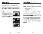
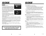
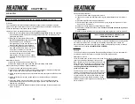
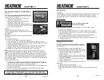
ELECTRONIC AQUASTAT CONTROLLER
Principles
The Electronic Controller displays the temperature of the
HTF in the water jacket and shuts down the fan(s) when
excessive low HTF is detected.
1) At its low setting it will turn the combustion air
blower(s) on, re-igniting the fire.
2) At its high setting it will turn the combustion air
blower(s) off, extinguishing the fire.
3) The difference between the highest temperature of the
HTF and the lowest temperature of the HTF is factory
set at 15 degrees Fahrenheit.
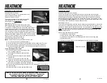
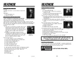
Operation
The factory settings on this aquastat should not be
changed; changing the factory settings will void the warranty
and certifications.
Maintenance
Keep the face of the dial clean by cleaning periodically with
glass cleaner.
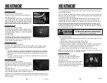
Removal and Replacement
1) Turn off the main power supply to the HEATMOR™.
2) Remove the screws from the panel that holds the Electronic Aquastat Controller.
3) Pull the controller and panel away from the housing to obtain clearance to work on the
Electronic Aquastat Controller on the back.
4) Disconnect and label or draw a diagram of each wife connection on the Electronic
Aquastat Controller. Refer to the Wiring diagram at the back of this manual.
5) Replace the controller and reverse the steps above for re-installation.
NOTE:
Different makes and models of furnaces may have different controllers. These
controllers will NOT be interchangeable. Replace with the correct unit from your dealer.
NOTE:
The temperature reading on the temperature gauge may not coincide exactly with
the temperature of the HTF leaving the back of the HEATMOR™ or the temperature of the
HTF arriving into the building being heated. There may also be small variances between
the temperature reading on the front of the HEATMOR™ and the high limit aquastats on the
back of the HEATMOR™.
These variances result from:
1) The Electronic Aquastat Controller is reading the temperature of the HTF at the top
of the water jacket, at the rear of the HEATMOR™. The hot supply HTF is taken from
the bottom of the water jacket at the rear of the HEATMOR™.
2) The high limit aquastat is reading the temperature from the top of the water jacket, at
the rear of the HEATMOR™.
3) Until the HTF is thoroughly mixed, whether or not the unit is firing, there will be
variances between the different instruments.
IN A NORMAL OPERATING MODE, SMALL VARIANCES IN READINGS AND
CALIBRATIONS WILL NOT AFFECT THE END RESULTS OF THE TOTAL SYSTEM.
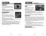
Electronic Aquastat Controller
Temperature Probe
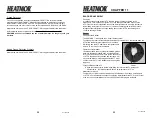
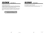
ELECTRICAL
Principles
The HEATMOR
TM
furnace comes with all internal components pre-wired. Provision is made
for easy attachment of the main electrical power supply to the HEATMOR™ controls.
Electrical outlets at the rear of the HEATMOR™ accommodate plugging in circulating
pumps.
Electrical Supply
Have a licensed electrician make
all electrical connections.
Required electrical power supply to the HEATMOR™ is 115 volts, 60HZ, 1 phase.
1) Use only 14/3 electrical wire.
2) The 14/3 wire will actually contain 4 wires; a) black, b) white, c) red, d) ground
3) If the electrical wire is being buried in the trench, be certain to use electrical wire
approved for direct burial.
4) Do not place electrical wire in close contact with the supply and return lines.
5) The electrical supply wire should be connected to it’s own circuit.
6) The red wire is used as a 120v signal back to the house that the Heatmor is in an
Over-Temp situation.
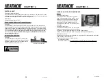
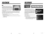
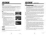
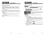
Electrical Supply Junction Box
Principles
The electrical components of the HEATMOR™ furnace are
pre-wired at the factory. All the wiring becomes centralized in
the junction box.
Connecting the main power supply to the HEATMOR™:
1) Remove the plate on the Electrical Supply Junction Box.
2) Insert the electrical supply wire through the hole in the
housing corner and route up the back into the
supply junction box.
3) Basically, the black wires are connected, the white wires
are connected, the ground wires are connected, and the
red wires are connected.
4) Tighten the screw clamp in the electrical connector to
hold the supply wire firm.
5) Replace the plate on the Electrical Supply Junction Box.
Maintenance
1) Keep the junction box clean and dry.
2) Keep the cover plate firmly attached at all times.
3) Make certain the MARR connectors (wire nuts) are properly installed and holding
tight.
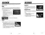
Electrical Supply Junction Box
CHAPTER 18