ADVANCED TROUBLESHOOTING CONTINUED
3. Thermostat is defective or not turned up to call for heat. Turn the thermostat up to the highest possible setting and try to start the heater.
Next set a multi-meter to measure voltage coming out of the thermostat. If approximately 120 volts is not measured, the thermostat is defec-
tive.
4. Control board is defective. Using a multi-meter set for volts, check the hot and neutral wires which bring voltage into the control board. If
proper voltage is reaching the board then the control board is defective.
5. Reset button has not been reset. Push the reset button and try to start the heater.
6. Wiring disconnected, loose or incorrect. With the heater unplugged, check the wiring from the cord to the terminal blocks, thermostat, and
flame/safety control. Consult the wiring diagram of your heater to make sure all these wires are connected properly.
Heater ignities, but flame is excessive.
Causes:
1. Pump pressure too high.
2. Incorrect fuel.
3. Worn nozzle.
.
Solutions:
1. Pump pressure too high.
Use a high pressure fuel gauge attached to the pump’s gauge port to check the pump pressure. Use the pump’s pressure adjustment if the
pressure is higher than the manufacturer’s recommended setting.
2. Incorrect fuel.
Only use fuels recommended by the specific manufacturer of the heater. Never use gasoline, thinners, solvents, or any other flammable fluid. If
you suspect incorrect fuel, inspect carefully, then drain and replace if necessary.
3. Worn nozzle.
Over time, impurities in the fuel which are forced thru the nozzle under high pressure will enlarge the orifice and cause the heater to overfire or
run “rich”. Always check first for excessive pump pressure or incorrect fuel. If the pressure and fuel are both correct, a new nozzle is needed.
DF400/DF600 Sequence of Operation
Step 1 - Plug in power cord.
Power flows thru the fuse to five places: the power indicator light, the fuel filter heating element,
the relay terminal #11, the electronic board and thru the control board to the three position on/off switch.
Step 2 - Turn switch to the On position.
There are two choices for On with this switch. Selecting the upper On position allows
for continuous operation without attaching an external thermostat control. The upper On position will return power from the
On/Off switch to the control board. This will cause the control board to begin the ignition sequence. Choosing the lower On posi-
tion will cycle the heater on and off with the attachment of an external thermostat control to the thermostat plug on the control
panel. When the external thermostat returns power to the control board the ignition sequence is initiated.
Step 3 - Control Board begins ignition sequence.
First the board sends power to the relay terminal #A1. This joins relay con-
tacts #11 and #14 sending power to the motor and transformer.
Step 4 - Control boards sends power to the solenoid valve.
After the motor and transformer have received power for approxi-
mately 7 to 10 seconds the control board will send power to the solenoid valve. If the airswitch closes, the power to the solenoid
valve must travel thru an air pressure switch to reach the valve. Air switch is in series with solenoid valve.
Step 5 - Photocell must detect flame.
After the control board sends power to the solenoid valve the photocell must detect the
presence of flame in about two seconds. If flame is not detected the reset light will come on and the control board will interrupt
power to the solenoid valve. The cool down phase will run as the control board will continue to power the relay and therefore the
motor for 90 seconds. When flame is detected by the photocell the control board will continue to power the solenoid valve, the
motor, and the transformer.
Step 6 - Turn Control Switch to Off position.
The control board removes power to the solenoid valve and runs the motor for 90
seconds.
10
Содержание DF400
Страница 5: ...5 ...
Страница 6: ...6 See page 11 ...
Страница 12: ...165 28 N 7 5 2 00 80ºS 190 Technical Specifications N 12 ...
Страница 14: ...14 DF400 Wiring Diagram SN 276000401 and Beyond CAPACITOR P N E10325 ...
Страница 15: ...15 DF600 Wiring Diagram SN 277000401 and Beyond CAPACITOR P N E10325 ...
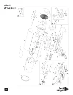
Страница 16: ...16 DF400 Breakdown ...
Страница 18: ...DF600 Breakdown 18 ...


