4/20/11
Heat & Glo • NorthStar EPA Fireplace • 480-1081E
Page 29
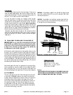
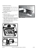
D cut side of timer shaft must face
away from the Linkage Timer Arm
3. Place linkage control arm over timer shaft and tighten
set screw. Figure 4.22.
Tighten set screw
Figure 4.22
1
2
3
4
5
3
4
5
6
7
8
9
10
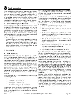
Figure 4.23 Exploded View of Entire Assembly for Point of Refer-
ence only
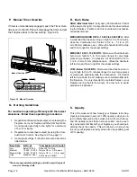
4. Rotate linkage control arm into final position and re-
attach to mounting plate. Note that the D cut is now
facing the linkage timer arm. Re-attach the linkage
timer arm. Figure 4.23
Item
Description
Qty
1
Door Linkage
1
2
Linkage Control Arm
1
3
Bushing
2
4
Washer SAE #10
2
5
Screw 8-32 x 1/2 PH PHL TC
2
6
Linkage Timer Arm
1
7
Attachment Nut & Set Screw
1
8
Screw 6-32 x 1/4 PH PHL TC
2
9
Mounting Bracket
1
10
Timer, Mechanical, 12 hours
1
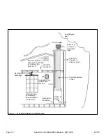
Figure 4.21

